Solver NEXT SPM. Instruction Manual
174
8.2.2.1. Selecting Lithography Mode
To select the lithography mode, perform the following steps:
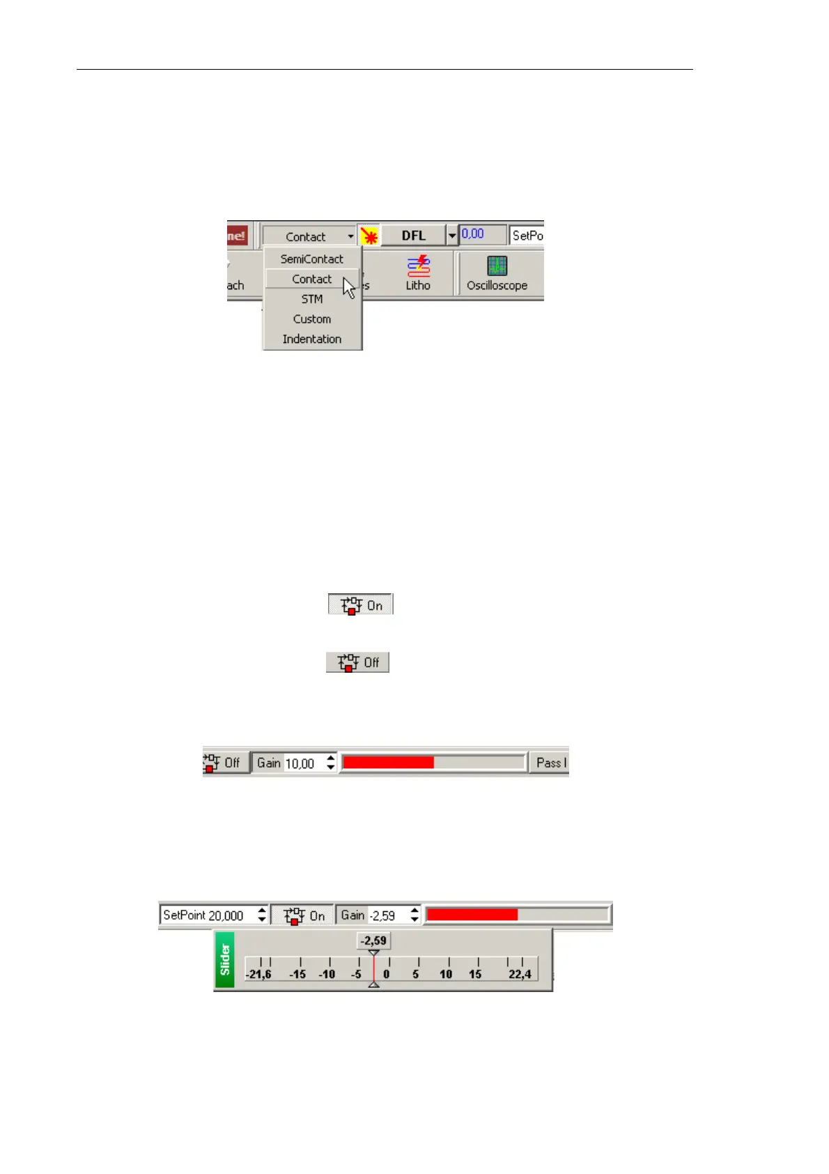
1. In the controller configuration drop-down list of the Nova P9 program, select Contact
(Fig. 8-10).
Fig. 8-10. Selecting the controller configuration
This will result in automatic configuring the software to operate in contact modes. The
parameters will be adjusted as follows:
● Output of the feedback loop – DFL signal;
● SetPoint parameter (proportional to the force applied to the sample) – 2 nA;
● Feedback Gain – minus 10.
2. Adjust the SetPoint level for the contact mode as follows:
a. Break the feedback loop (the button will change its appearance to Off);
b. Adjust the SetPoint level to be 0.5 lower than the current DFL level;
c. Close the feedback loop (the button will change its appearance to On);
d. Increase the SetPoint level and watch extension of the Z scanner section in the
indicator of the Main Operations panel (Fig. 8-11). Set the
SetPoint parameter at
the level when extension of the Z scanner section stops.
Fig. 8-11. Scanner extension indicator
3. Adjust the working level of the feedback gain (Gain parameter) as follows:
a. Double-click in the input field of the Gain parameter. This will open the adjusting
slider of the feedback gain (Fig. 8-12).
Fig. 8-12. Adjusting slider of the
Gain parameter
b. Decrease the Gain level gradually and watch the input of the feedback loop in the
sofware oscilloscope.