Chapter 8. Lithography
175
c. Find the Gain level when oscillations starts. This level is featured by a noticeable
oscillating component of the input signal.
d. Enter the working level to be 0.5÷0.7 of the threshold level of the Gain parameter at
which the oscillations starts.
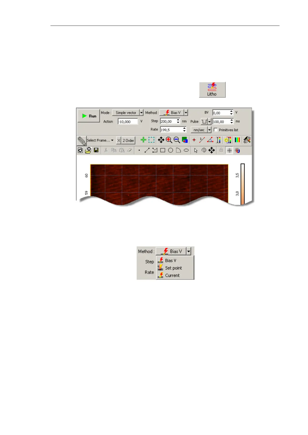
4. Open the Litho window (Fig. 8-13) by clicking the button in the Main
Operations panel.
Fig. 8-13.
Litho window
5. For Force lithography, select SetPoint in the Method drop-down list (Fig. 8-14).
Fig. 8-14. Selecting the lithography method
NOTE. Appearance of the Control panel of the Lithography window depends on the
selected mode of vector lithography.
6. In the Mode drop-down list, select the desired mode of vector lithography (Fig. 8-15).
For vector lithography, for modes are provided:
● Simple vector – simple vector lithography. The force applied to the sample is
constant during drawing objects;
● Gradient – gradient lithography. The force applied to the sample ramps linearly
during drawing objects;
● Pulse – pulse lithography. The sample is exposed to a series of force pulses of the
same amplitude during drawing objects;