Chapter 8. Lithography
181
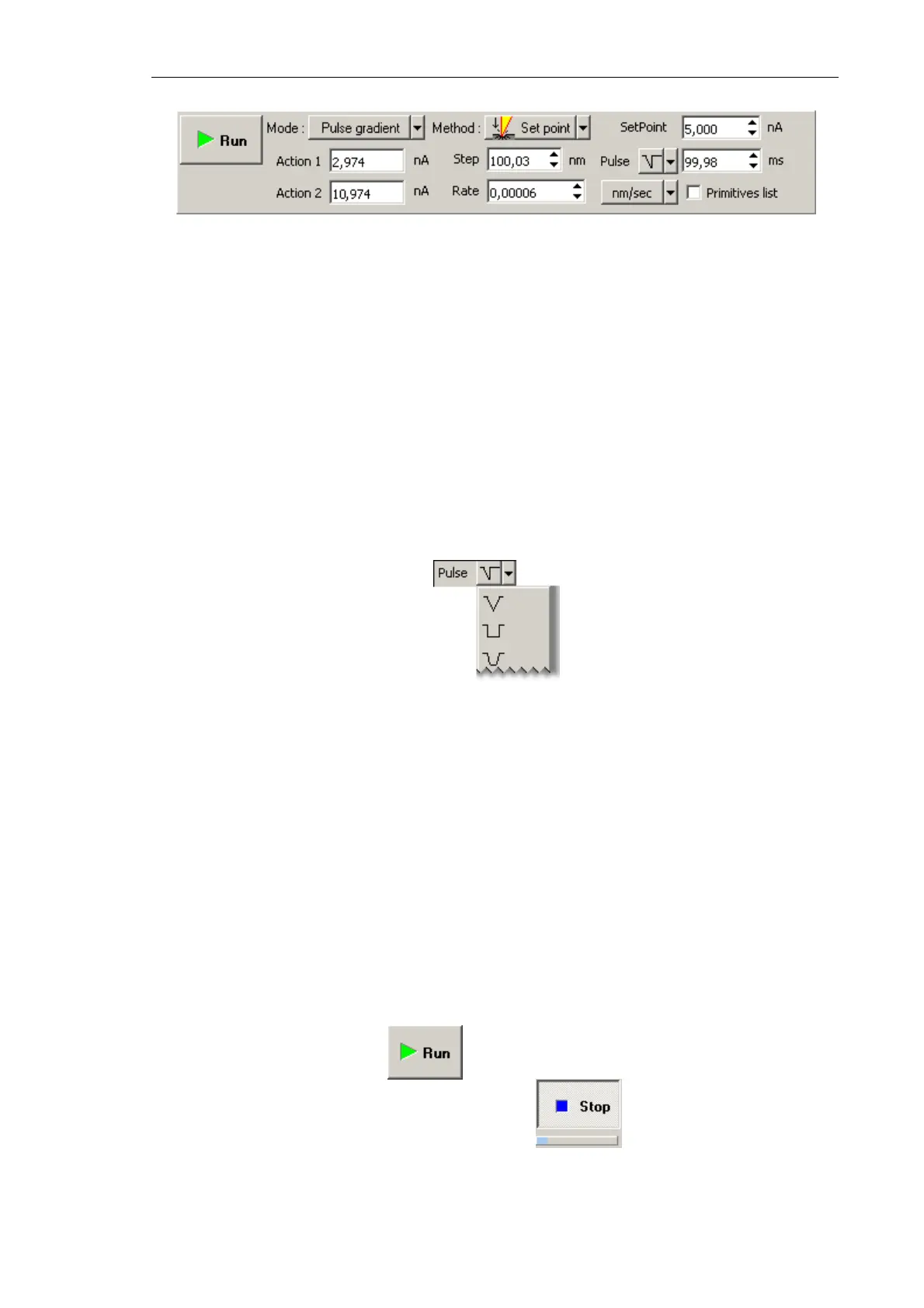
Fig. 8-24. Lithography Control panel
2. In the SetPoint field (Fig. 8-24), define the force applied to the sample when the probe
moves to starting points of the template objects after finishing drawing or at the start of
lithography.
3. In the Rate field (Fig. 8-24), define the lithography rate (the speed of moving the probe
relative to the sample surface).
The lithography rate influences on results of the sample exposure to lithography. The
lower is the rate, the deeper is the exposure and the better is the correspondence
between the template and the resulting surface.
4. In the Step field, define the time step between the pulses (Fig. 8-24).
5. In the drop-down list to the right from the Step field, select the desired pulse shape.
Fig. 8-25. Pulse shape
6. In the
Pulse field (Fig. 8-24) define duration of a pulse.
8.2.2.4. Performing Lithography
When the lithography template is prepared (see i. 8.2.2.2 on p. 176) and the lithography
parameters are adjusted (see i. 8.2.2.3 on p. 178), the operator can start the lithography
process.
Operations of the lithography procedures are the same for all modes.
To start lithography, click the button in the Control panel of the Litho window.
This will change appearance of the Run button to . Below the Stop button, the
progress bar will appear to display percentage of the procedure progress in blue.