Solver NEXT SPM. Instruction Manual
180
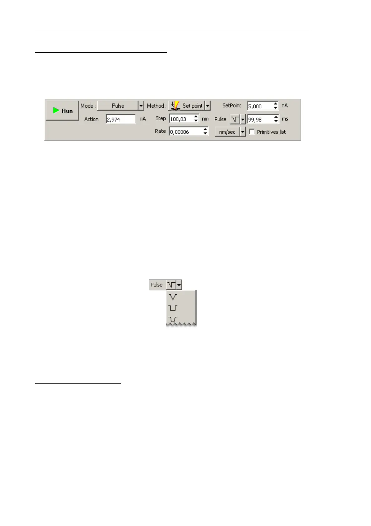
Adjusting Pulse Lithography Parameters
1. In the Action field of the lithography Control panel, define the force applied to the
sample during drawing the template objects (Fig. 8-22).
Relation between pressure on the sample and the Action value is given in i. 8.2.1.2
“Preliminary Scanning and Selecting Lithography Region” on p. 172.
Fig. 8-22. Control panel for Pulse Vector lithography
2. In the SetPoint field (Fig. 8-22), define the force applied to the sample when the probe
moves to starting points of the template objects after finishing drawing or at the start of
lithography.
3. In the Rate field (Fig. 8-22), define the lithography rate (the speed of moving the probe
relative to the sample surface).
The lithography rate influences on results of the sample exposure to lithography. The
lower is the rate, the deeper is the exposure and the better is the correspondence
between the template and the resulting surface.
4. In the Step field, define the time step between the pulses (Fig. 8-22).
5. In the drop-down list to the right from the Step field, select the desired pulse shape.
Fig. 8-23. Pulse shape
6. In the Pulse field (Fig. 8-22) define duration of a pulse.
Pulse-gradient lithography
1. In the Lithography Control panel, define the range of varying the force applied to the
sample. Define the lower boundary of the range in the Action 1 field and the higher
boundary in the Action 2 field (Fig. 8-24).
Algorithm of estimating the range of pressure on the sample related to the range of
Action values is given in i. 8.2.1.2 «Preliminary Scanning and Selecting Lithography
Region» on p. 172.