Chapter 7. Performing Measurements
107
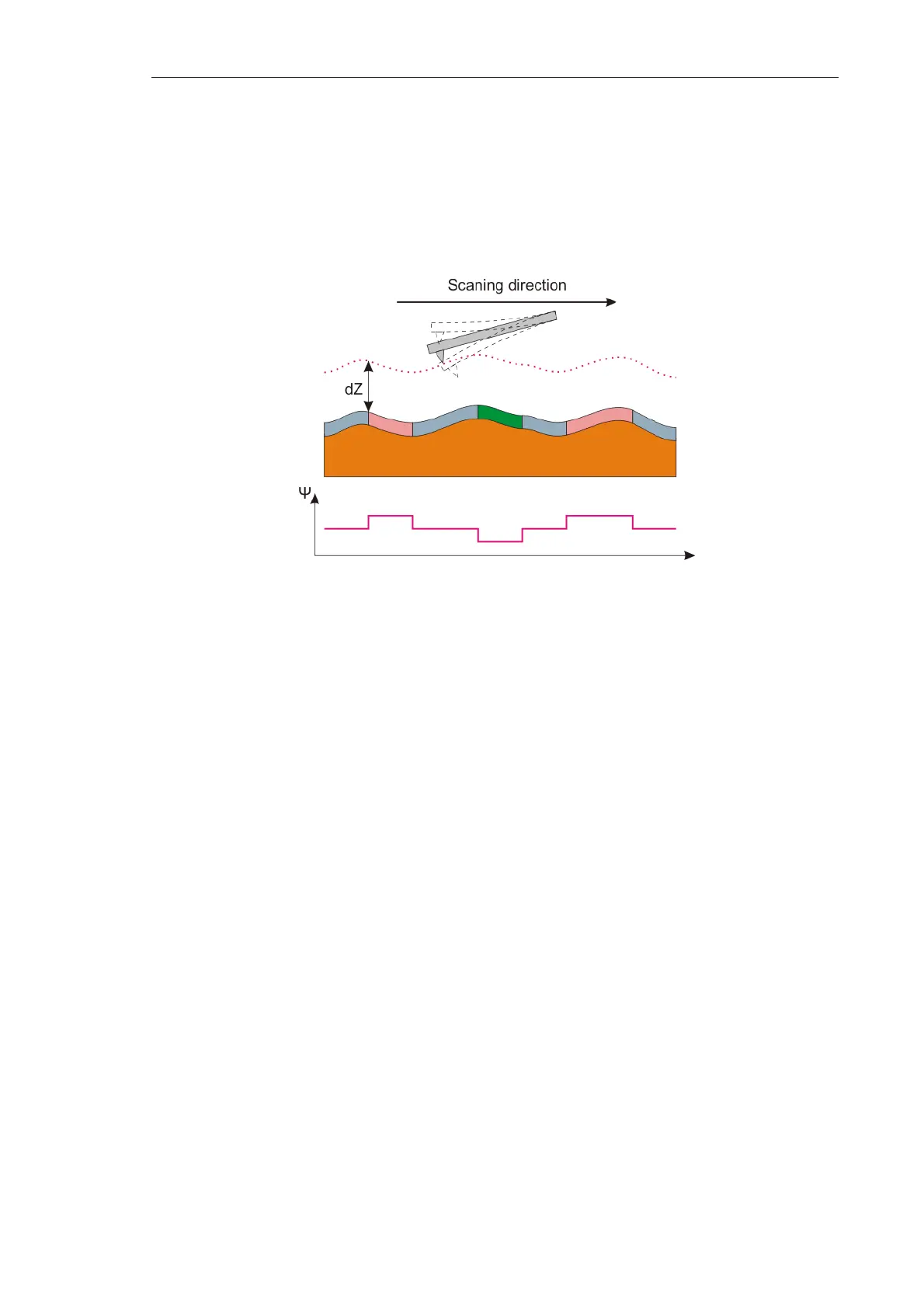
Then, the probe is lifted above the surface to the height dZ. In the second pass, the probe
moves over the surface along the same line following the surface topography contour (see
Fig. 7-77) maintaining the surface-probe distance constant. This distance should be big
enough to eliminate the surface topography influence. The probe is only affected by long-
range forces whose most prominent yield is due to magnetic forces of the sample. On the
other hand, the value of dZ should not be too great as that would reduce the measured
signal and impair the lateral resolution.
Fig. 7-77. Second pass
Ψ – phase shift
In the second pass, the piezodrive excites oscillation of the probe at its resonance
frequency. Imaging of the Z-component of the magnetic forces gradient on the sample
surface is performed through data on variations of the probe oscillation phase.
7.3.1.2. Procedural Sequence
MFM uses magnetic probes which are typically made of silicon coated with a thin
magnetic film.
Preparing the instrument for operation and measuring in the MFM Mode are generally
similar to those of the SemiContact Mode, which are described in detail
in item. 7.2.1 “Semicontact Mode” on p. 84 . A sequence of basic procedures, along with a
detailed description of instrument adjustment and specifics of MFM measurements,
is provided below.
Measurement in the MFM Mode is arranged in the following procedural sequence:
1. Preparing for Measurements (see Chapter 6 on p. 29).
2. Semicontact Mode (see i.. 7.2.1 on p. 84).
3. Approaching the Sample to the Probe (see i.7.1.1.3 on page 58).
4. Scanning (see i. 7.3.1.4 on p. 109).
5. Saving Measurement Data (see i. 7.2.1.7 on page 100)
6. Completing Measurements (see i. 7.2.1.8 on page 101)