Solver NEXT SPM. Instruction Manual
132
2. Gradually increase the Gain level and watch the IProbe level in the software
oscilloscope.
NOTE. The
Gain
level should be positive in STM mode.
3. Determine the value of the Gain parameter at which noise generation occurs. The
beginning of the generation is identified by appearance of a noticeable alternating
component in the IProbe signal.
4. Decrease the value of the Gain parameter to 0.5÷0.7 of the threshold. This value will be
used in further operation.
7.4.1.4. Adjusting Scanning Parameters
Adjusting the feedback input
1. Open the feedback loop by releasing the button .
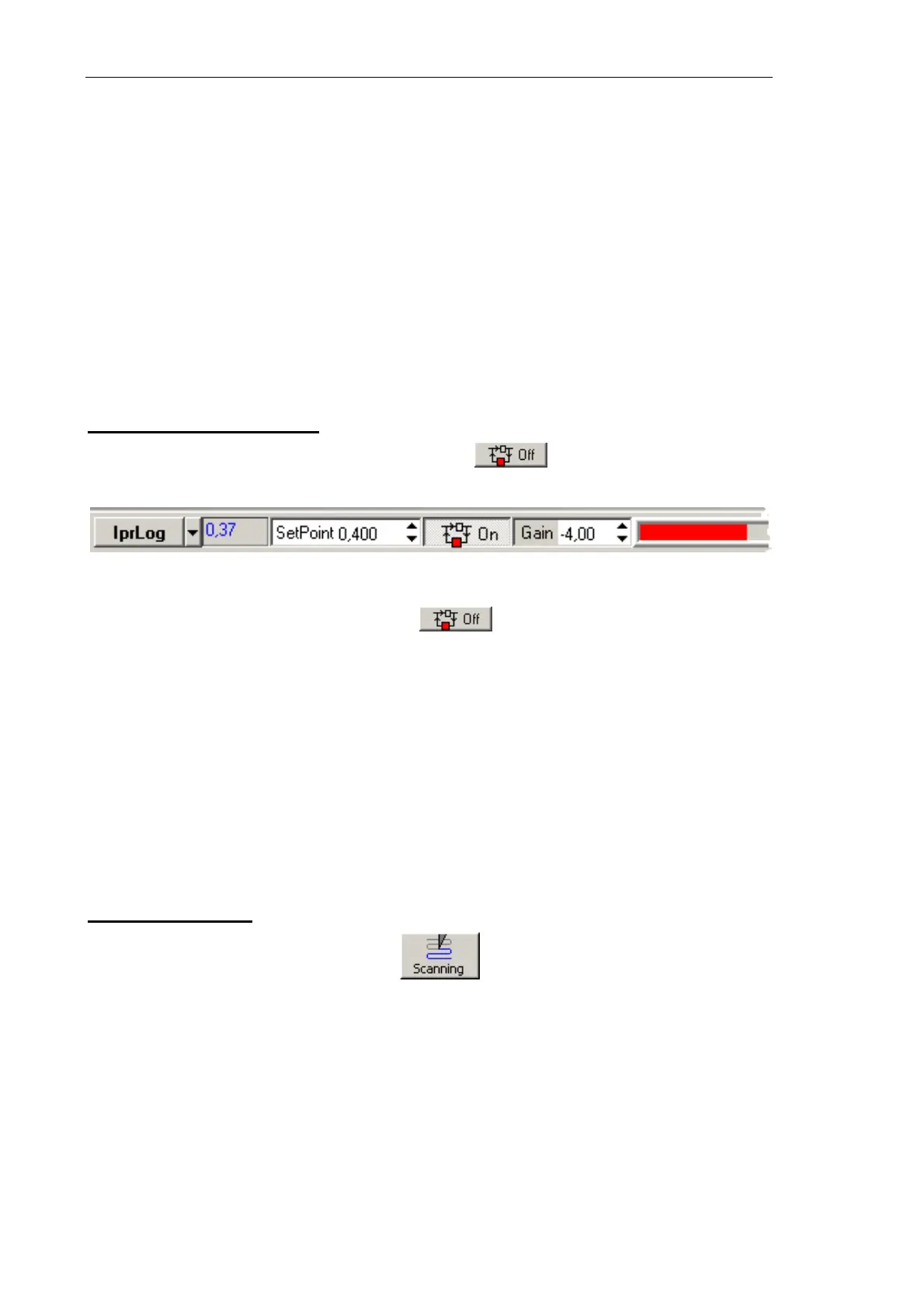
2. Select the
IprLog signal as the feedback input (see Fig. 7-111).
Fig. 7-111. Selecting the feedback input
3. Close the feedback loop by pressing the button.
4. Observe the IProbe signal with the software oscilloscope and adjust the SetPoint
parameter so that the IProbe level is 0.1 nA. Usually, with this level of the IProbe
current the SetPoint parameter is about 20.
5. Increase the Gain value and watch the IProbe value in the software oscilloscope.
6. Determine the value of the Gain parameter at which noise generation occurs. The
beginning of the generation is identified by appearance of a noticeable alternating
component in the IProbe signal.
7. Decrease the value of the Gain parameter to 0.5÷0.7 of the threshold. This value will be
used in further operation.
Selecting STM mode
Open the Scan window by clicking the button in the Main Operations panel.
The top part of the Scanning window contains a panel, which provides control over
scanning process (see Fig. 7-112). A data viewer is below the Control panel.
Select the
STM Topo mode in the Mode list of the Control panel of the scanning window
(see Fig. 7-112). This results in automatic performing all necessary switching sequences in
the controller.