Solver NEXT SPM. Instruction Manual
56
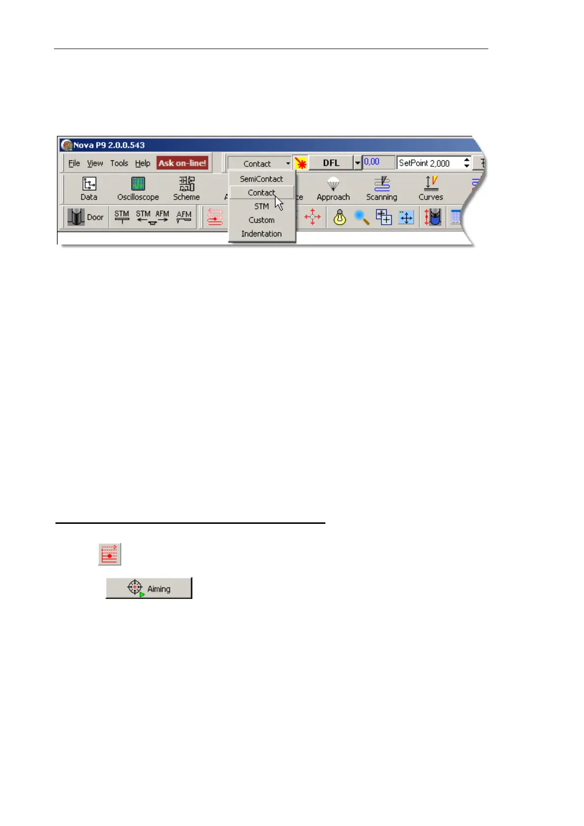
7.1.1.1. Adjusting the Controller Configuration
Switch the instrument for operating in the Contact technique by selecting Contact in the
controller configuration list (see Fig. 7-1) at the top bar of the Main Program window.
Fig. 7-1. Selecting the controller configuration
Once the configuration Contact is set, all switching sequences required for the instrument
to operate in contact modes proceed automatically.
7.1.1.2. Adjusting Initial Level of the DFL Signal
Initial level of the DFL signal corresponds to the state of the cantilever oscillating freely.
Its value depends on the photodiode position relative to the cantilever reflected beam. The
DFL level is zero when the laser spot is halved by the top and the bottom parts of the
photodiode, that is, the corresponding integral intensities are equal.
Initial level of the DFL signal can be adjusted either automatically or manually.
Adjusting initial level of the DFL signal automatically
Automatic adjustment of the DFL signal uses the
Laser/Diode scan window that opens
with the button.
Click the button. This launches the photodiode movement motors and
the photodiode will be repositioned so as the laser spot is centered at the photodiode and
the DFL level is close to zero.
The Laser Aiming window displays the adjusting process (see Fig. 7-2).