Chapter 7. Performing Measurements
77
7.1.4.2. Preparation for Measurements
The Contact Error Mode is based on the Constant Force Mode, which is described in detail
in i. 7.1.1 “Constant Force Mode” on page 55.
Before the Contact Error Mode measurements, prepare for the measurements and perform
measurements of surface topography by the Constant Force Mode.
After the completion of preliminary measurements of surface topography by the Constant
Force Mode, perform setting of parameters for operating by the Contact Error Mode.
7.1.4.3. Scanning
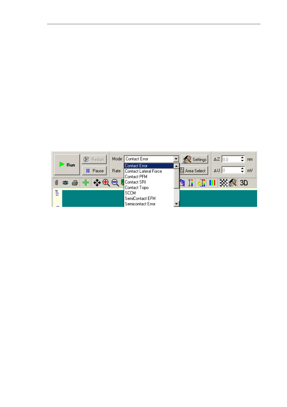
Select the Contact Error mode in the Mode list on the Control panel of the Scanning
window (Fig. 7-32). For this cofiguration, the DFL signal will be used as the second
detection signal for the first scan pass.
Fig. 7-32. Selecting the
Contact Error Mode
Click the button Run to trigger the process of scanning.
The following actions take place:
● Line-by-line scanning of the sample surface starts and two images appear in the field of
2D visualization of the scanning data. One of the images is an image of surface
topography (signal
Height), while the other one is the error signal (signal DFL)
(Fig. 7-33);