Chapter 6. Preparing for Measurements
37
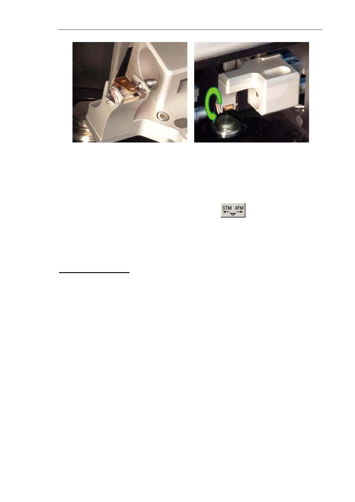
Fig. 6-21 Fig. 6-22
AFM probe is now installed.
NOTE. If the AFM probe is not planned to work after installation, it is recommended to
withdraw it to its inoperative position by clicking the button on the Measuring
heads control panel (see Fig. 6-4).
6.4.2. Installing the STM Tip
Manufacturing the Tip
The STM tip is the sharpened end of a piece of platinum-iridium (PtIr), or platinum-
rhodium (PtRo) (with platinum content of about 80 %) or tungsten (W) wire, 8÷10 mm in
length with a diameter of 0.25÷0.5 mm.
The sharpness of the tip can be estimated by imaging a reference sample with known
surface characteristics, for example, Highly Oriented Pyrolytic Graphite (HOPG).
There are two techniques of manufacturing an STM tip:
1. By cutting the wire apex with scissor (PtIr, PtRo) (see below).
2. By electrochemical etching (W, Pt, PtIr, PtRo).
The simplest STM tip manufacturing technique is cutting the wire apex with the scissors.
This provides the apex radius of curvature less than 10 nm.
Sharp-edged scissors and tweezers with kinks on the interior surface (see the toolkit
supplied with the instrument) are used to cut the wire.