Chapter 8. Lithography
179
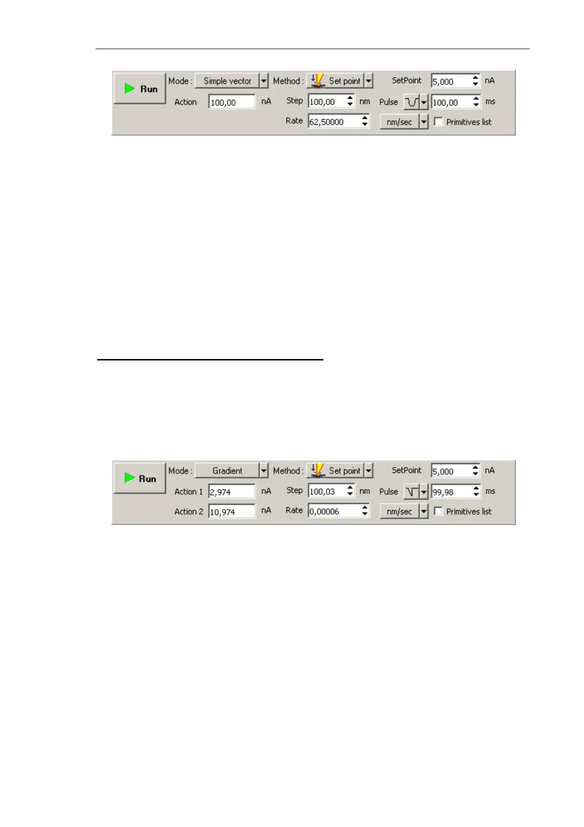
Fig. 8-20. Control panel for Simple Vector lithography
2. In the SetPoint field, define the force applied to the sample when the probe moves to
starting points of the template objects after finishing drawing or at the start of
lithography.
3. In the Rate field, define the lithography rate (the speed of moving the probe relative to
the sample surface).
The lithography rate influences on results of the sample exposure to lithography. The
lower is the rate, the deeper is the exposure and the better is the correspondence
between the template and the resulting surface.
NOTE. The parameters
Step
and
Pulse
are irrelevant for the Simple vector lithography.
Adjusting Gradient Lithography Parameters
1. In the Lithography Control panel, define the range of varying the force applied to the
sample. Define the lower boundary of the range in the Action 1 field and the higher
boundary in the Action 2 field (Fig. 8-21).
Algorithm of estimating the range of pressure on the sample related to the range of
Action values is given in i. 8.2.1.2 “Preliminary Scanning and Selecting Lithography
Region” on p. 172.
Fig. 8-21. Control panel for Gradient Vector lithography
2. In the SetPoint field, define the force applied to the sample when the probe moves to
starting points of the template objects after finishing drawing or at the start of
lithography.
3. In the Rate field, define the lithography rate (the speed of moving the probe relative to
the sample surface).
The lithography rate influences on results of the sample exposure to lithography. The
lower is the rate, the deeper is the exposure and the better is the correspondence
between the template and the resulting surface.
NOTE. The parameters
Step
and
Pulse
are irrelevant for the Gradient vector lithography.