Chapter 7. Performing Measurements
111
The value of the ac component, U
1
·sin(ωt), of the bias voltage should be big enough to
induce oscillations of the probe. Frequency of the ac electric field is selected to be equal to
the resonance frequency of the probe.
Once amplitude of the oscillation becomes zero at some value of the dc bias, this voltage
U
0
is equal to the local surface potential. Influence of surface topography features on the
measurement data is eliminated with using the two-pass measurement scheme.
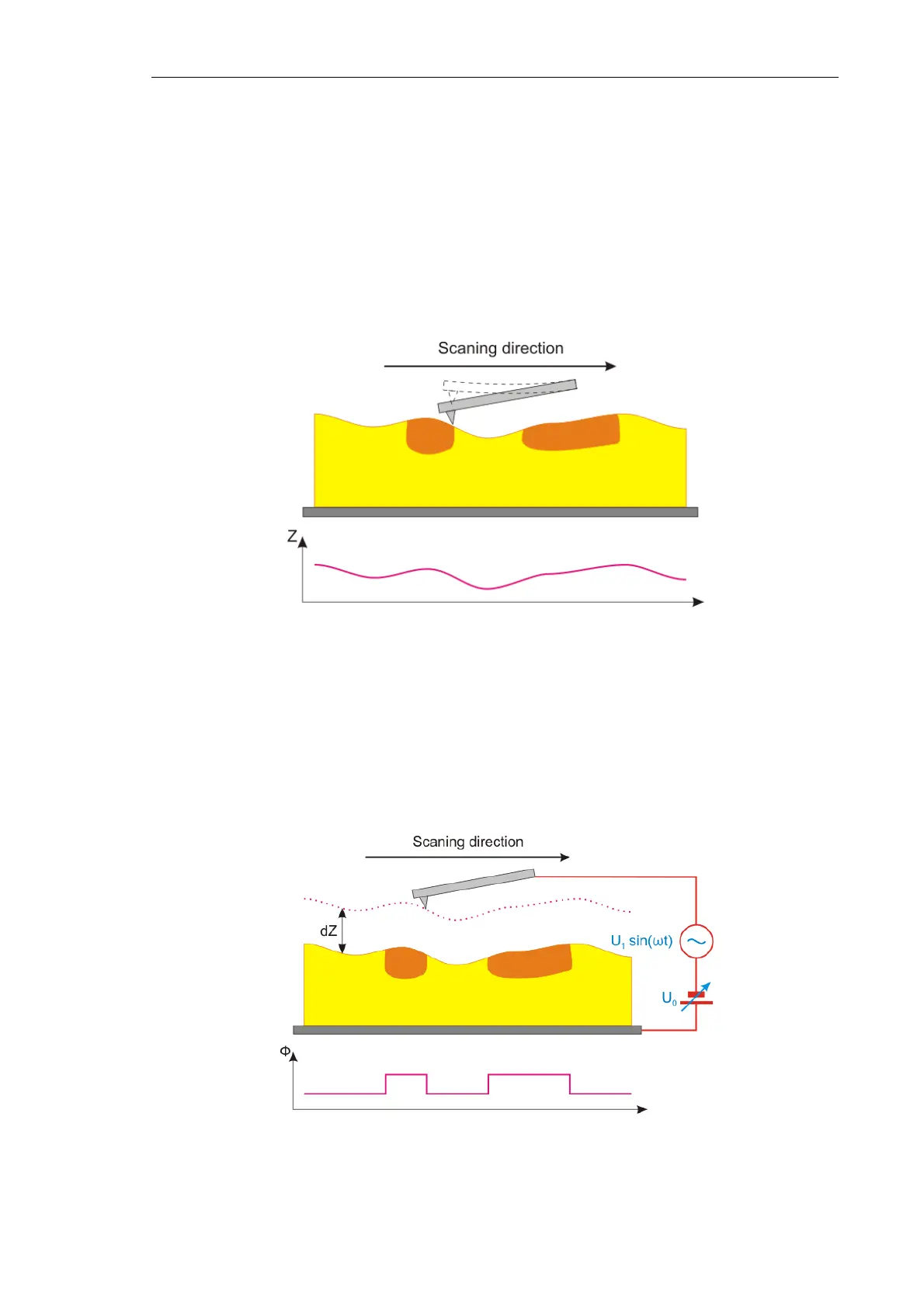
Scanning proceeds as follows. In the first pass, surface topography of the scan line is
measured in the SemiContact Mode (see Fig. 7-82).
Fig. 7-82. First pass
Surface topography imaging
Then, the probe is lifted above the surface to the height dZ. An ac voltage U
1
·sin(ωt) is
applied to the probe. This voltage induces oscillations of the probe at its resonance
frequency ω. The probe oscillation amplitude is maintained equal to zero through the
feedback loop by altering the dc component of the bias voltage U
0
(x,y). The probe moves
over the surface following the surface topography contour (see Fig. 7-83).
Fig. 7-83. Second pass
Ф – Surface potential