Chapter 1. Overview
7
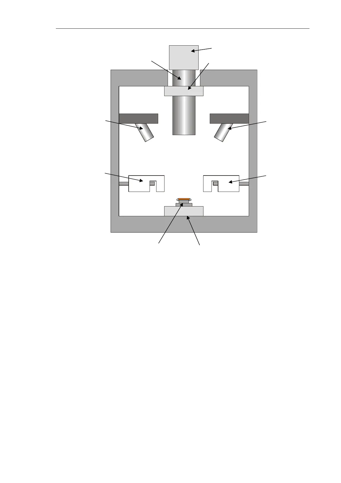
Fig. 1-2. Schematic diagram of the Solver NEXT
The sample to study is fixed on a metal substrate that is mounted on the sample holder. The
sample holder is fastened to the upper end of the piezo scanner that operates in the
“scanning-by-sample” mode.
The positioning system allows moving the sample in the XY plane to select the
investigation area as well as displacing the sample vertically to approach it to the probe.
The built-in optical viewing system serves for selecting the scan area on the sample
surface. The optical microscope of this system is equipped with a positioning system that
provides selection of the scan area on the sample surface.
The Solver NEXT measuring unit is equipped with two measuring heads, for atomic-force
microscopy (AFM) and for scanning tunneling microscopy (STM). Availability of two
built-in measuring heads enables quick exchange of the experimental technique and does
not need special training of the operator.
Auxiliary measuring heads (for liquid environment and for nanoindenting) extend range of
the instrument capabilities. With those heads, measurements in liquids as well as hardness
measurements or modification of the sample surface are available.
Sample
Video camera
Optical microscope
Sample positioning system
Optical microscope
positioning system
Laser
Photodiode
STM measuring
hea
AFM measuring
head