Solver NEXT SPM. Instruction Manual
184
2. Adjust the SetPoint level for the contact mode as follows:
a. Break the feedback loop (the button will change its appearance to Off);
b. Adjust the SetPoint level to be 0.5 lower than the current DFL level;
c. Close the feedback loop (the button will change its appearance to On);
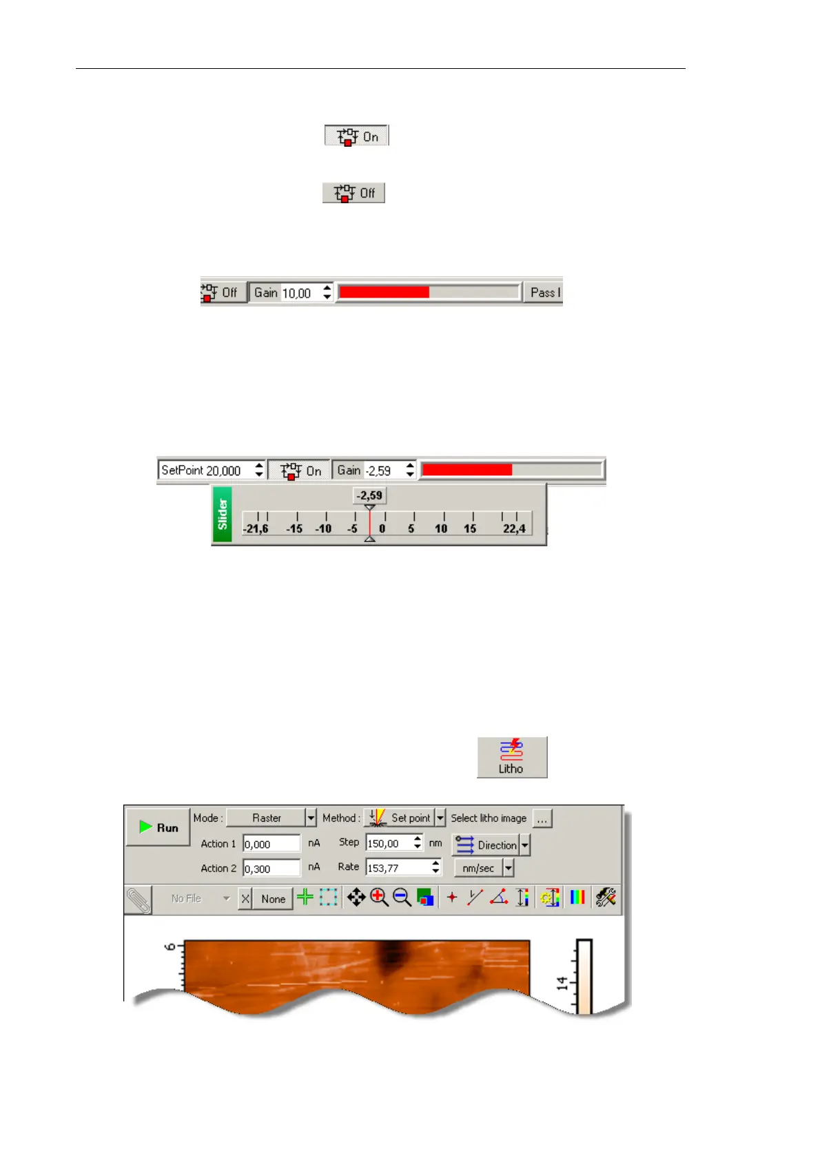
d. Increase the SetPoint level and watch extension of the Z scanner section in the
indicator of the Main Operations panel (Fig. 8-11). Set the SetPoint parameter at
the level when extension of the Z scanner section stops.
Fig. 8-28. Scanner extension indicator
3. Adjust the working level of the feedback gain (Gain parameter) as follows:
a. Double-click in the input field of the Gain parameter. This will open the adjusting
slider of the feedback gain (Fig. 8-29).
Fig. 8-29. Adjusting slider of the
Gain parameter
b. Decrease the Gain level gradually and watch the input of the feedback loop in the
sofware oscilloscope.
c. Find the Gain level when oscillations starts. This level is featured by a noticeable
oscillating component of the input signal.
d. Enter the working level to be 0.5÷0.7 of the threshold level of the
Gain parameter at
which the oscillations starts.
4. Open the Litho window (Fig. 8-30) by clicking the button in the Main
Operations panel.
3
Fig. 8-30.
Litho window