Solver NEXT SPM. Instruction Manual
190
Selecting the lithofraphy region for charge lithography
Charge lithography will be explained with a GaAs sample and a probe of NSG01/TiN
model. Charge lithography will cause accumulation of electrical charge in the subsurface
layer under the exposing tip.
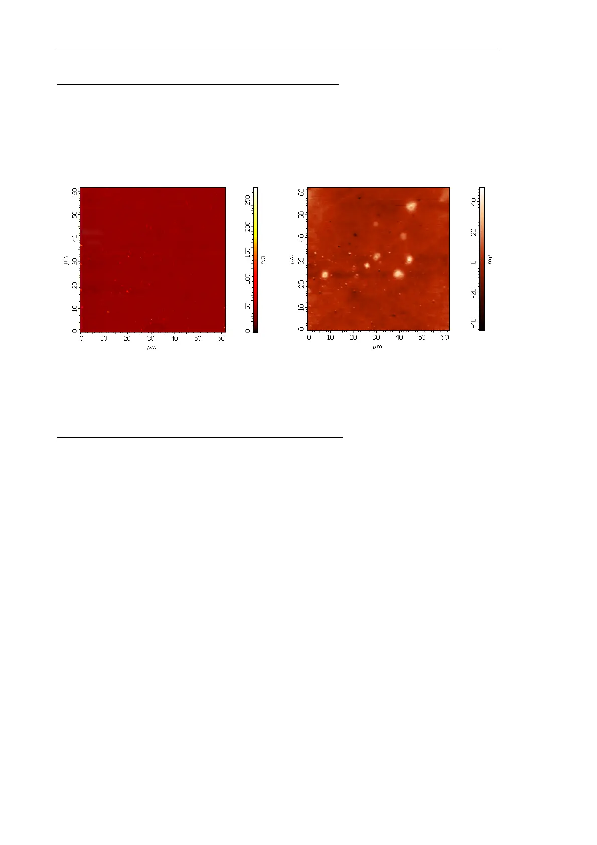
Preliminary scanning provides the surface topography and the surface potential distribution
of the region selected for topography (Fig. 8-37).
Fig. 8-37. Sample image before lithography
left – topography; right – surface potential distribution
Selecting the lithofraphy region for current lithography
Current lithography will be explained with a octadecyltriclorsylanum sample and a probe
of DCP11 model. Current lithography will result in changing surface properties of the
sample monolayer. The surface portions exposed to voltage will transform from
hydrophobic to hydrophilic, thus providing modulation of friction and contarast for Lateral
Force Microscopy.
Preliminary scanning provides the lateral force distribution (LF signal) of the region
selected for topography.