3 Nomenclature and Functions
3-10
CJ2 CPU Unit Hardware User’s Manual
• There is no priority to the order in which the errors are displayed. All of the errors are displayed
repeatedly in sequence.
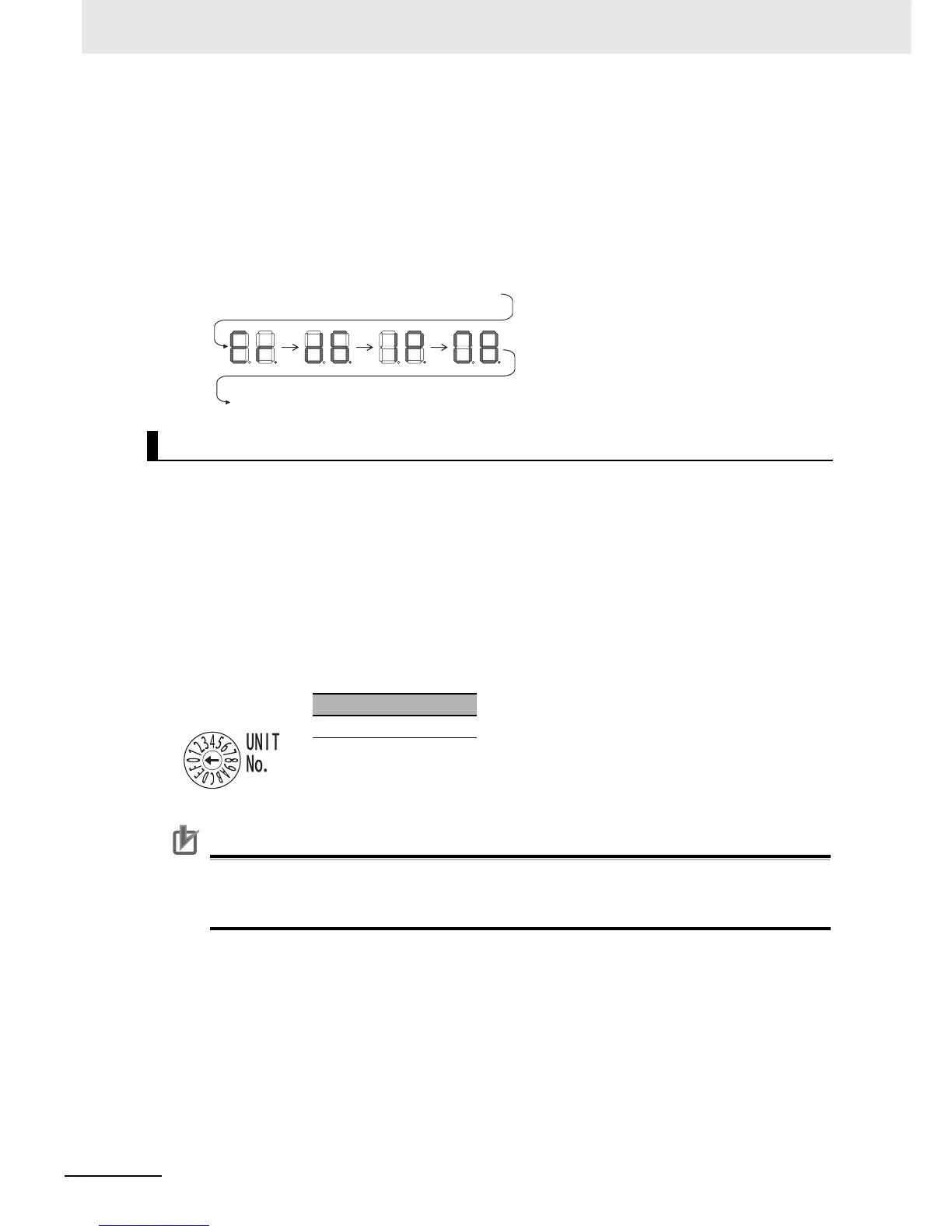
Left/Right Dot LEDs
If an error occurs at multiple devices for which the rightmost 8 bits in the IP addresses are the same,
this is indicated by the dots on the right side in display on the target devices.
The following examples show the displays for multiple errors.
• d6 errors (failure to connect) have occurred in communications with IP address 10.0.1.8.
• d6 errors (failure to connect) have occurred in communications with IP address 10.0.2.8.
The unit number and node address for the CJ2 CPU Unit built-in EtherNet/IP port are set using the
rotary switches. The unit number and node address are allocated in the same way as for a CPU Bus
Unit. According to the unit number that is set, words are automatically allocated in the CIO Area and
DM Area. For details, refer to the CJ2 CPU Unit Software User’s Manual (Cat. No. W473).
z Setting the Unit Number
Set a unique unit number for the CJ2 CPU Unit built-in EtherNet/IP port. The same unit number can-
not be used by any other CPU Bus Unit connected to the CJ2 CPU Unit.
Use a small screwdriver to make the setting, and be sure not to damage the rotary switch. The unit
number is factory-set to 0.
Precautions for Correct UsePrecautions for Correct Use
• Always turn OFF the PLC’s power supply before setting the unit number.
• When setting the unit number for the first time or when changing the setting, create the PLC’s
I/O tables.
z Node Address Setting Switches
Set a FINS address for the built-in EtherNet/IP port. With the FINS communications service, multiple
EtherNet/IP Units (including the CJ2 Unit built-in EtherNet/IP port) connected by Ethernet are identi-
fied by their node addresses. Using the node address switches, set a unique node address in hexa-
decimal. The same node address cannot be used by any other EtherNet/IP Unit or Ethernet Unit
connected on the same Ethernet network.
Rotary Switches
Setting range
0 to F