80
Unit Components Section 2-2
3. Terminating Resistance Switch
Set this switch to ON only for double-ended connection to a Host Link net-
work. This switch is factory-set to OFF.
4. RS-485 Interface Switch
Used to switch to the RS-485 interface, and to enable or disable RS/CS
control when performing RS-485 communications.
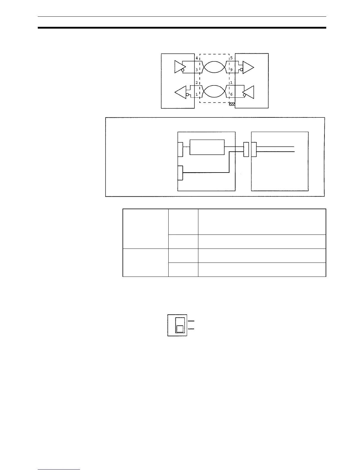
RS-422/485 Connection Example
CPM2C-CIF11 B500-AL004
Shield
Connector hood
Internal Configuration
CPM2C-CIF11 CPM2C CPU Unit
RS-422/485 port
(terminal block)
RS-232C port
(D-sub connector)
CMOS level →
RS-422 conversion
Peripheral port
(CMOS level)
RS-232C port
(RS-232C)
RS-422/485 port
on CPM2C-
CIF11
Signal
conversion
Converts CMOS level (CPU Unit side) to RS-422
(connected device side).
RS-422 (externally connected device) insulated
using DC/DC converter or photocoupler.
Function Host Link, peripheral bus, or no-protocol connec-
tions.
RS-232C port on
CPM2C-CIF11
Signal
conversion
Outputs signals from the CPU Unit’s CMOS interface
without conversion.
Function Host Link, no-protocol, 1:1 Link, or 1:1 NT Link con-
nections.
SW1
ON
OFF
Terminating Resistance
RS-422: 235
Ω (combined
resistance must be 110
Ω min)
RS-485: 118
Ω (combined
resistance must be 54
Ω min)