139
Wiring and Connections Section 3-4
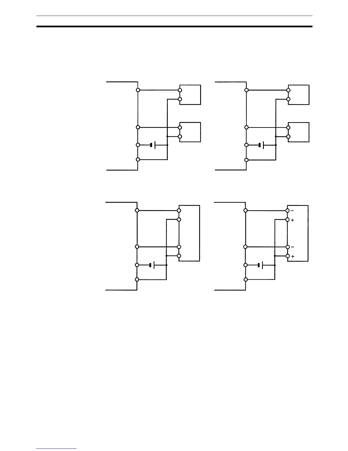
Using Pulse Outputs The following diagrams show example applications of sink-type transistor out-
puts using output bits IR 01000 and IR 01001. Use the PULS(65), SPED(
−−),
ACC(
−−), PWM(−−), and SYNC(−−) instructions to produce pulse outputs
(rather than normal outputs) from output bits IR 01000 and IR 01001.
Note *CW is clockwise and CCW is counter-clockwise.
Output Wiring
Precautions
Observe the following precautions to protect the PC’s internal components.
Output Short Protection
The output or internal circuitry might be damaged when the load connected to
an output is short-circuited, so it is recommended to install a protective fuse in
each output circuit. Use a fuse that has a capacity of about twice the output
ratings.
CPM2C
Single-phase pulse output
(Fixed duty ratio)
Motor driver
Pulse output 0:
01000
CPM2C
Pulse output 1:
01001
COM
Motor driver
Single-phase pulse output
(Variable duty ratio)
Relay
Pulse output 0:
01000
CPM2C
Pulse output 1:
01001
COM
Relay
Pulse plus direction output
Motor driver
Pulse output 0:
01000
CPM2C
Direction output:
01001
COM
Direction
input
Increment pulse output
Motor driver
CW* pulse output:
01000
CCW* pulse output:
01001
COM
CW input
CCW input
24 V
24 V
24 V 24 V