230
Unit Components and Functions Section 7-2
Note RS-422 and RS-485 communications cannot be used together.
2. RS-232C Port
Outputs the CPU Unit’s RS-232C port interface. Connects to an RS-232C
interface on a computer, PT (Programmable Terminal), etc.
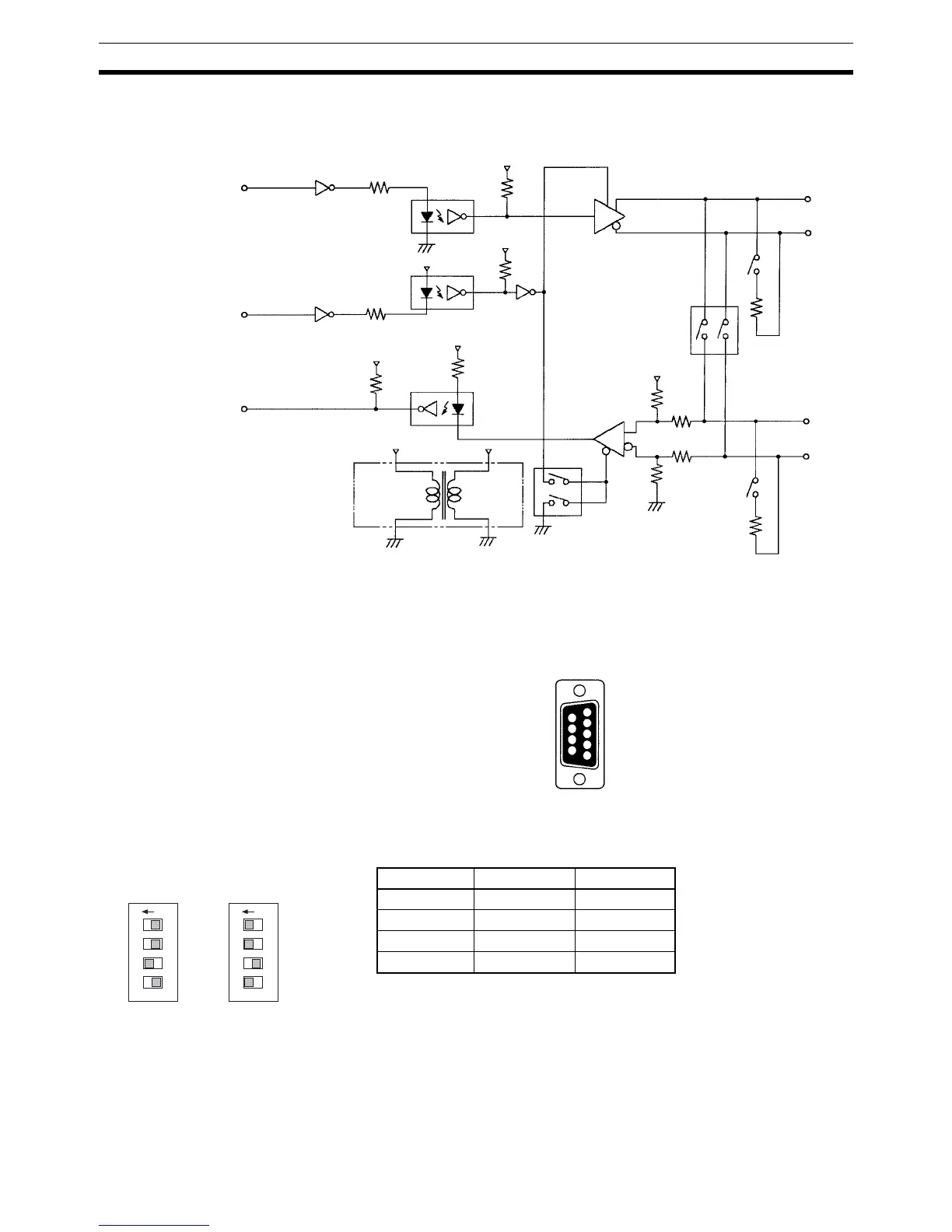
3. RS-422/RS-485 Switch (SW1)
Switches the RS-485 interface and sets RS/CS controls for the RS-485 in-
terface.
Note Do not turn ON both SW1-3 and SW1-4 at the same time. Doing so will
destroy internal circuits. The default setting is for RS-485.
RS-422 Interface Block Diagram
TxD
SE
RxD
0 V
C5V
5 V
5 V
C5V
0 V
C0V
C0V
C0V
SW4
C5V
C5V
C5V
SDB
SDA
SW4
SW1
12
RDB
RDA
SW1
4
3
5 V
Pin on SW1 RS-422 RS-485
1OFFON
2OFFON
3ONOFF
4OFFON
Pin Assignments
9 SG
8 NC
7 NC
6 NC
5 CTS
4 RTS
3 RxD
2 TxD
1 NC
ON 1 2 3 4
ON 1 2 3 4
SW1 SW1
RS-422 Setting RS-485 Setting