231
Unit Components and Functions Section 7-2
4. CPU Unit Connector
Connects to CPU Unit communications port.
Note Do not mount or remove connectors for the CPU Unit while power is supplied.
Normal communications may not be possible and devices may malfunction.
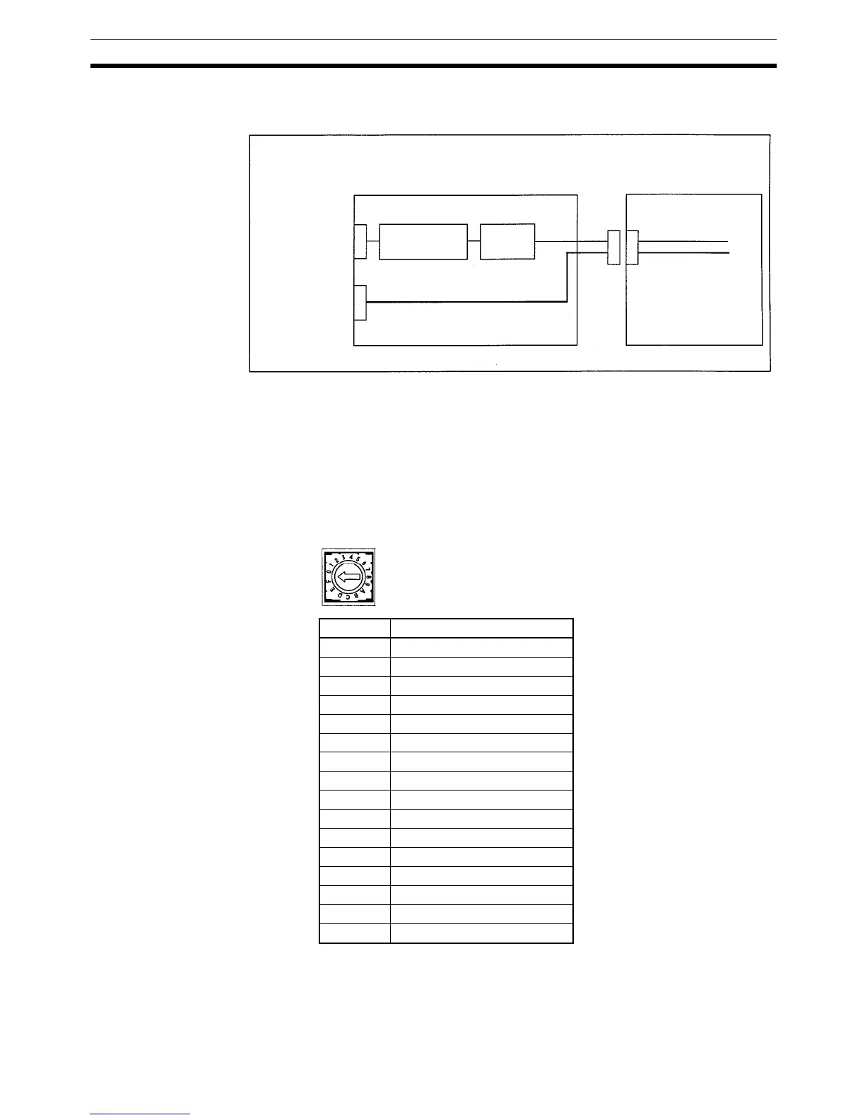
5. DM Area Setting Switch (SW2)
Sets the starting word in the DM Area that is used to exchange data be-
tween the Simple Communications Unit and CPU Unit. The following table
shows the relationship between the rotary-switch setting and starting DM
Area word.
Internal Configuration Diagram
CPM2C-CIF21
CPM2C CPU Unit
RS-422/RS-485
port
(Terminal block)
RS-232C port
(D-Sub connector)
CMOS-level to
RS-422 converter
Internal
micro-com-
puter
Peripheral port
(CMOS level)
RS-232C port
(RS-232C)
Setting Starting word in DM Area
0 DM 0000
1 DM 0100
2 DM 0200
3 DM 0300
4 DM 0400
5 DM 0500
6 DM 0600
7 DM 0700
8 DM 0800
9 DM 0900
A DM 1000
B DM 1100
C DM 1200
D DM 1300
E DM 1400
F DM 1500
SW2