26
Comparison with the CPM1A and CPM2A Section 1-5
Note The setting of SW2 will affect the operating mode for all Units with lot numbers
of 3180O (31 August 2000) or earlier. Refer to
1-7 Changes in SW2 for
details.
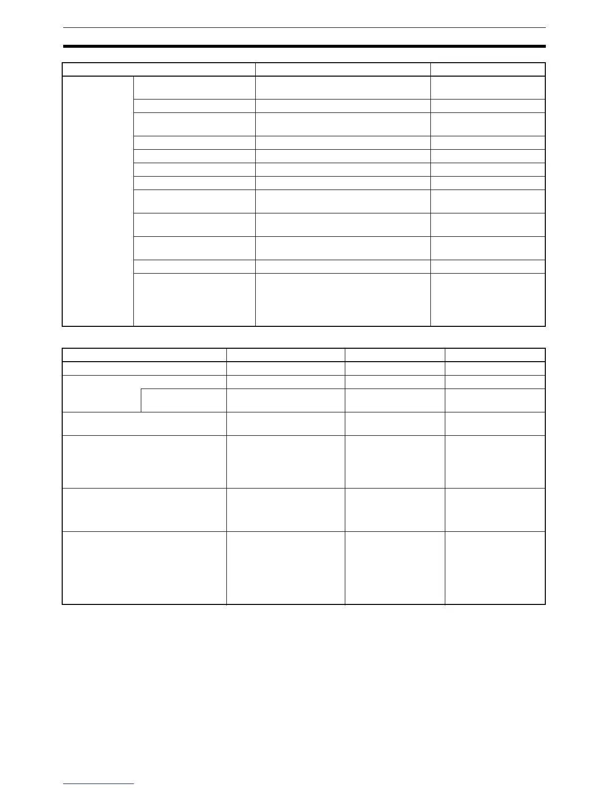
Pulse output
control
Trapezoidal acceleration/
deceleration
Supported with ACC(−−). The initial fre-
quency can be set.
Not supported.
PWM(−−) output Supported. Not supported.
Number of simultaneous
pulse outputs
2 max. 1 max.
Maximum frequency 10 kHz max. 2 kHz max.
Minimum frequency 10 Hz 20 Hz
Pulse output quantity –16,777,215 to 16,777,215 0 to 16,777,215
Direction control Supported. Not supported.
Positioning to absolute posi-
tions
Supported. Not supported.
Bit status while pulses are
being output
No effect Turned ON/OFF by pulse
output
Reading PV Read SR 228 through SR 231 or execute
PRV(62).
Not supported.
Resetting PV Supported. Not supported.
Status outputs Accelerating/decelerating
PV overflow/underflow
Pulse quantity set
Pulse output completed
Pulse output status
Pulse output status
Item CPM2C/CPM2A CPM1A
Item CPM2C CPM2A CPM1A
Analog controls None 2 2
Clock function Internal or none Internal None
Words containing
time info.
AR 17 to AR 21 AR 17 to AR 21 ---
Analog I/O Analog I/O Units can be
connected.
Same as CPM2C. Same as CPM2C.
Temperature monitoring The CPU Unit can receive
temperature sensor input
from either thermocouples
or platinum resistance ther-
mometers.
Same as CPM2C. Same as CPM2C.
CompoBus/S communications A CompoBus/S I/O Link Unit
can be connected to provide
CompoBus/S Slave func-
tions.
Same as CPM2C. Same as CPM2C.
Communications switch This switch determines
whether communications
are governed by the stan-
dard settings or PC Setup
settings. Also sets the Pro-
gramming Device connec-
tion. (See note.)
This switch determines
whether communica-
tions are governed by
the standard settings or
PC Setup settings.
None