79
Setting Control Specifications Section 4-3
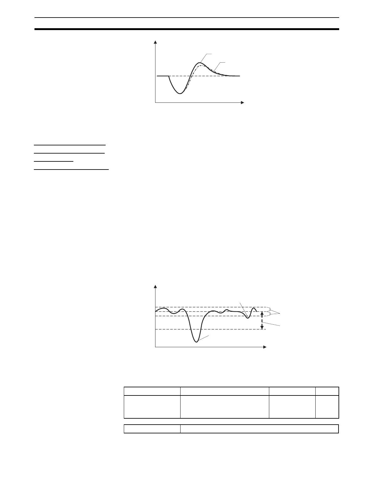
Note The waveform shown in the diagram above will vary depending on the control
object's characteristics and the PID constant settings.
Starting Conditions
for the Disturbance
Overshoot
Adjustment Function
The Disturbance Overshoot Adjustment Function will operate after the pro-
cess value (PV) has stabilized in the Disturbance Rectification Band and the
deviation is larger than the Disturbance Judgment Width.
• When the Disturbance Judgment Width is positive, the Disturbance Over-
shoot Adjustment Function will operate if a disturbance causes the pro-
cess value (PV) to fall. When the Disturbance Judgement Width is
negative, the Disturbance Overshoot Adjustment Function will operate if a
disturbance causes the process value (PV) to rise.
• The Disturbance Overshoot Adjustment Function will not operate in the
following situations:
• When the Disturbance Rectification Band or Disturbance Judgment
Width parameter is 0
• When the set point is changed (when the set point change width ex-
ceeds the Disturbance Rectification Band)
• During autotuning
• During ON/OFF control
• During PD control (I = 0.0)
4-3-10 Operation during Errors
This parameter can be used to select the operation when an error occurred.
Note This parameter can be set only when operation is stopped.
When this parameter has been changed, the new setting becomes effective
0
SP
Temperature
Disturbance Time Constant = 1
Time
Disturbance Time Constant =
SP
Temperature
Time
The Disturbance Overshoot Adjustment Function does not operate.
The Disturbance Overshoot Adjustment Function operate.
Disturbance Rectification
Band
Disturbance Judgment
Width
Variable type Parameter name Setting range Default
F0/B0
Operation During Error (Selection B)
(Common)
0: Notification only
(continue)
1: MV at PV Error
2: Stop control
0
Conditions for use There must be a CT input.