53
Setting Input Specifications Section 4-1
Note This parameter can be set only when operation is stopped.
Always set the Scaling Upper Limit > Scaling Lower Limit.
If the Scaling Lower Limit > Scaling Upper Limit, the larger value will function
as the Scaling Upper Limit.
■ Setting Example
In this example, scaling is set to display 0 to 5 V as 10.0% to 95.0%.
Scaling Upper Limit = 950
Scaling Lower Limit = 100
Decimal Point Position = 1
4-1-4 Input Shift (Correction)
If there is a significant difference between the temperature at the measure-
ment point and the location where the temperature display is needed so that
the display/control performance is unsatisfactory at the present sensor posi-
tion (measurement point), the temperature difference can be set as an input
shift (correction) value.
Note The decimal point position is determined by the sensor selection. With analog
inputs, the decimal point position is determined by the Decimal Point Position
parameter setting. In this case, however, the 0 (****) decimal point position
setting will be treated as setting 1 (***.*).
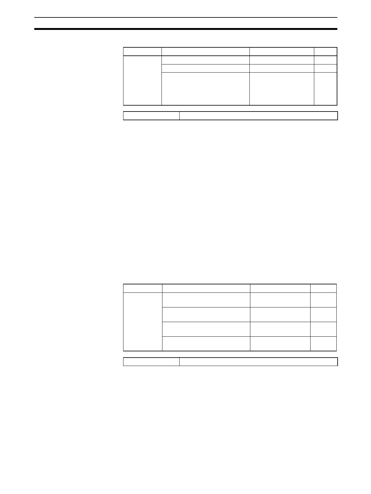
Variable type Parameter name Setting range Default
E0/A0
(See note.)
Scaling Upper Limit (Channel) −1999 to 9999 1000
Scaling Lower Limit (Channel) −1999 to 9999 0
Decimal Point Position (Channel) 0: ****.
1: ***.*
2: **.**
3: *.***
1
Conditions for use The input type must be set to analog input.
Variable type Parameter name Setting range Default
D5/95 Input Value 1 for Input Correction
(Channel)
−1999 to 9999 EU 0
Input Shift 1 (Channel) −1999 to 9999 EU
(See note.)
0
Input Value 2 for Input Correction
(Channel)
−1999 to 9999 EU 1000
Input Shift 2 (Channel) −1999 to 9999 EU
(See note.)
0
Conditions for use No special conditions