42
Control Linked to a Host Device Section 3-3
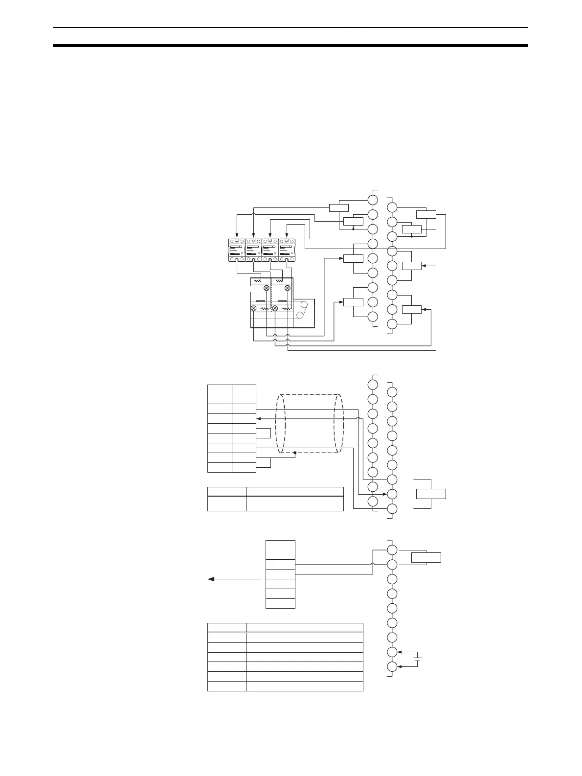
3-3-2 Wiring
Connect the Temperature Sensors to the input terminals according to the sen-
sor's input type.
• Connect the Solid State Relays to the output terminals.
• Connect the PLC with an RS-232C communications cable.
Wire the circuits as shown below when using an EJ1@-HFU and three EJ1@-
TC4 Units.
(The following diagram shows the wiring for just one of the EJ1@-TC4 Units.)
Note Port B cannot be used when the HFU (EJ1@-HFU) is used.
B1
B2
B3
B4
B5
B6
B7
B8
B9
OUT2
OUT1
IN2
IN1
A1
A2
A3
A4
A5
A6
A7
A8
A9
OUT4
OUT3
IN4
IN3
EJ1@-TC4
B1
B2
B3
B4
B5
B6
B7
B8
B9
A1
A2
A3
A4
A5
A6
A7
A8
A9
EJ1@-HFU
SD
RD
RS
CS
SG
FG
FG
Signal
2
3
4
5
9
Shell
1
Pin
Serial Communications
Board/Unit
SD
RD
SG
RS-232C
Shield
SW2
●SW2 settings (EJ1@-HFU)
Description
8 ON: RS-232C is selected.
1
2
3
4
5
6
7
8
9
EJ1C-EDU
24 VDC
RDA−
RDB+
SDA−
SDB+
Signal
FG
RS-485
● DIP Switch Settings (CJ1W-CIF11)
Pin Description
1 ON: Terminator connected.
2 ON: 2-wire method
3 ON: 2-wire method
4 Not used
5
OFF: No RS control of RD (continual reception)
6 ON: RS control of SD
+
−
Temperature
Sensor
Heater
SSR
G3NA
To NS8
communications
port A
CJ1W-CIF11