101
Other Functions (TC4 and TC2) Section 4-7
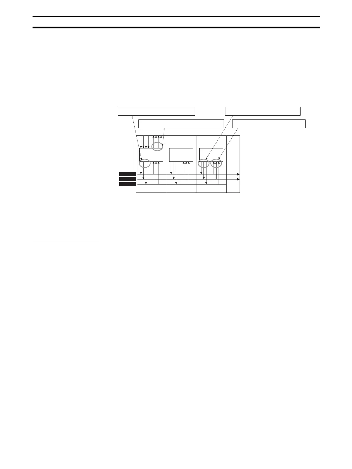
4-7-3 Internal Buses (TC4 and TC2)
The EJ1 has three built-in buses. I/O can be allocated to these buses, so sim-
ple sequences can be created by assigning signals that are output to the bus
(Bus Output Assignments) and assigning functions that operate according to
bus signals (Bus Input Assignments).
Note (1) Bus inputs cannot be used if a Basic Unit is used without an HFU.
Even if an HFU is used, bus inputs cannot be used for Basic Units con-
nected to the RS-485 communications lines using distributed positioning.
(2) BUS1 and BUS2 are connected to SUB1 and SUB2 on the EDU.
(3) HFU and TC2 event inputs and auxiliary outputs can be linked.
(4) Signals output to the bus can also be read at the outputting Unit itself.
Bus I/O Assignments The following diagrams show the parameters that can be set in the Bus Input
1 to 3 Assignment and Bus Output 1 to 3 Assignment parameters. Refer to the
Example on page 103, when setting parameters.
The settable parameters include those for all channels and those for individual
channels.
Note (1) Bus inputs cannot be used if a Basic Unit is used without an HFU.
Even if an HFU is used, Bus Input cannot be used for TC Units connected
to the RS-485 communications lines using distributed positioning.
(2) Set the bus settings correctly in each Unit so that there are no conflicts in
operation within the EJ1 system.
CPUCPUCPU
BUS1
BUS2
BUS3
SUB1
SUB2
EV SUB
HFU TC2 TC4 EDU
Set using bus input assignments.
Set using bus output assignments.
Set using auxiliary output assignments.
Set using bus output assignments.