60
Setting Output Specifications Section 4-2
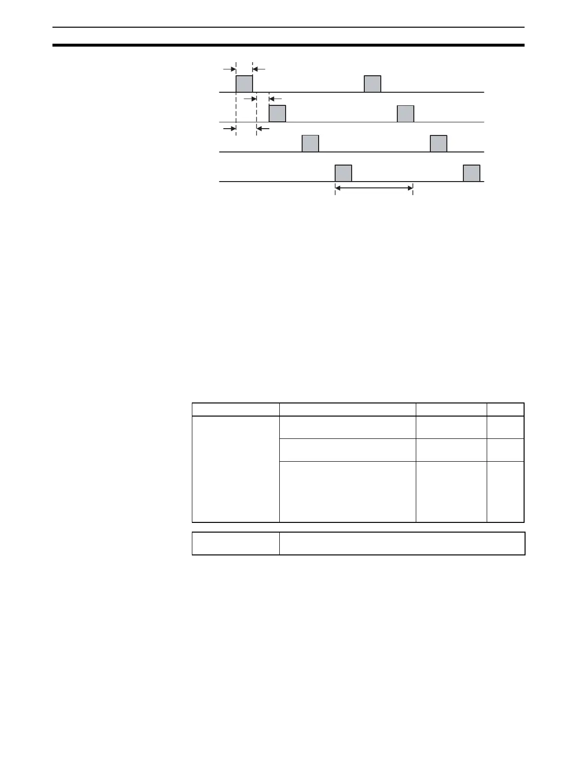
Note The Delay between Outputs parameter can be set to offset the ON
time for each output. The delay between outputs will, however, cre-
ate an OFF period between outputs, making it appear that the con-
trol period has increased. The actual power is 2/(10 + 4)
× 100 =
14.2%.
4-2-4 Output Scaling
A slope (gradient) and offset can be set for each value selected with the con-
trol output assignment.
The value selected with the control output assignment will be 100% when it
equals the Output Scaling Upper Limit and the value will be 0% when it equals
the Output Scaling Lower Limit.
The decimal point positions for the Output Scaling Upper and Lower Limits
are set with the Decimal Point C1 to C4 parameters. Change the decimal
point position setting if necessary.
Note (1) These parameters can be set only when operation is stopped.
(2) Use 40% AT when output scaling has been set. If 100% AT is used, hunt-
ing will occur.
OUT1
2 s=10 s × 20%
Delay between Outputs: 1,000 ms = 1 s
2.5 s=10 s × 25%
Control period: 10 s
OUT2
OUT3
OUT4
Variable type Parameter name Setting range Default
E1/A1 Output Scaling Upper Limit 1 to 4
(I/O)
−1999 to 9999 100
Output Scaling Lower Limit 1 to 4
(IO)
−1999 to 9999 0
Decimal Point C1 to C4 (IO) 0: **** (no deci-
mal point)
1: ***.*
2: **.**
3: *.***
0
Conditions for use The Control Output Assignment must be set to Control output
(heating) or Control output (cooling)