56
Setting Input Specifications Section 4-1
Input Value 2 for Input Correction = Controller readout (A) = 500°C
Input Shift 2 = Object temperature (B) - Controller readout (A) =
550°C
− 500°C = 50.00°C
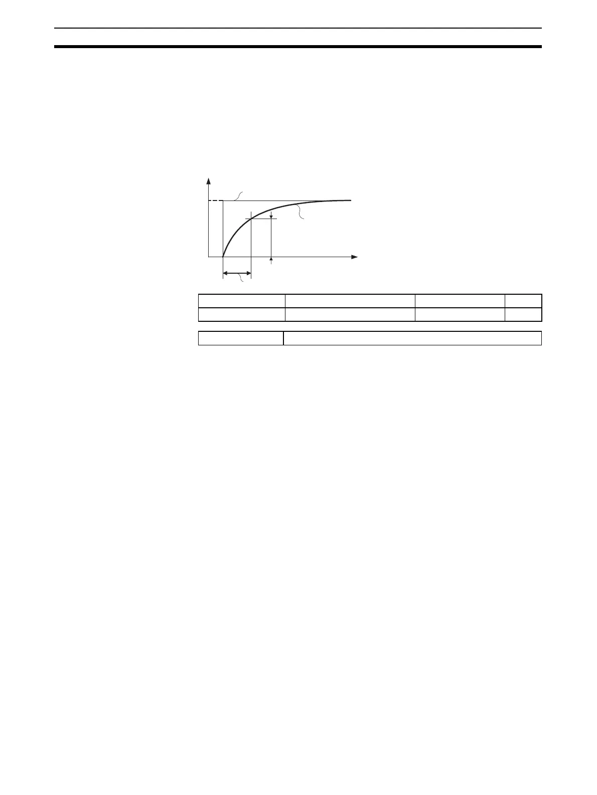
4-1-5 Input Filter
Sets the time constant of the digital input filter.
The following diagram shows the response of the digital filter to a step-wise
input of amplitude A.
Variable type Parameter name Setting range Default
D5/95 Input Digital Filter (Channel) 0.0 to 999.9 Second 0.0
Conditions for use No special conditions
Time
A
(Time
constant)
0.63 A
PV before passing through filter
PV after passing through filte
Input digital filter