7
I/O Configuration and Main Functions Section 1-2
• The End Unit has two communications ports: port A and port B. Write
Mode is valid for port B. If settings are changed from port A, they are
always written to EEPROM. When using port A, be sure to consider the
write life of the EEPROM.
• Two communications ports are provided for port A: a connector and termi-
nal block connections.
• The connector communications port can be used as a tool port. The End
Unit can be connected to a computer via a special E58-CIFQ1 USB-Serial
Conversion Cable to make EJ1 settings using the EST2-2C-MV3 CX-
Thermo Support Software.
• The terminal block communications port can be used to wire between
more than one EJ1 for distributed positioning of the EJ1. Up to 64 HFUs
and Basic Units can be connected this way.
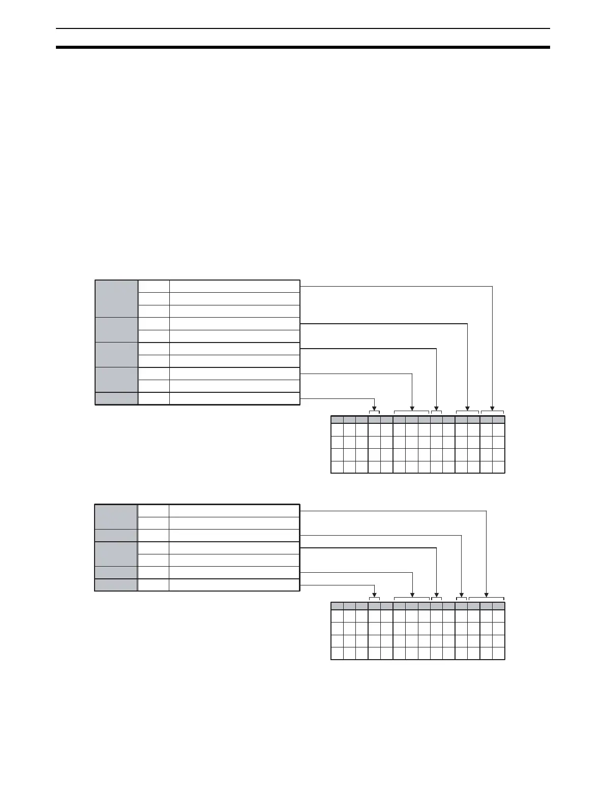
1-2-3 Model Number Legend
TC4 and TC2
HFU
B
H
Q
N
A
B
T C 4
T C 2
N
N - T C 4 A Q Q1JE -
1 2 3 4 5 6 7 8 9 10 11 12 13 14
N - T C 4 B Q Q1JE -
N - T C 2 A Q N H B1JE -
N - T C 2 B Q N H B1JE -
Options
None
2 CT inputs
2 event inputs
Outputs
2 pulse voltage outputs
2 transistor outputs
Terminal
type
Screw-less clamp terminals
Screw terminals
Unit name
Type Standard control
Four-channel Temperature Control Unit
Two-channel Temperature Control Unit
FL2
N
HFU
A
B
N
Outputs
CompoWay/F (RS-422)
FLK
Communications
CompoWay/F (RS-485/RS-232C)
4 transistor outputs
Terminal
type
Screw terminals
Screw-less clamp terminals
Unit name
Type
Standard control
Advanced Unit
N - H F U A N F1JE -
1 2 3 4 5 6 7 8 9 10 11 12 13 14
N - H F U A N F1JE -
N - H F U B N F L K1JE -
N - H F U B N F L 2
LK
L2
1JE -