16
Wiring Terminals Section 2-2
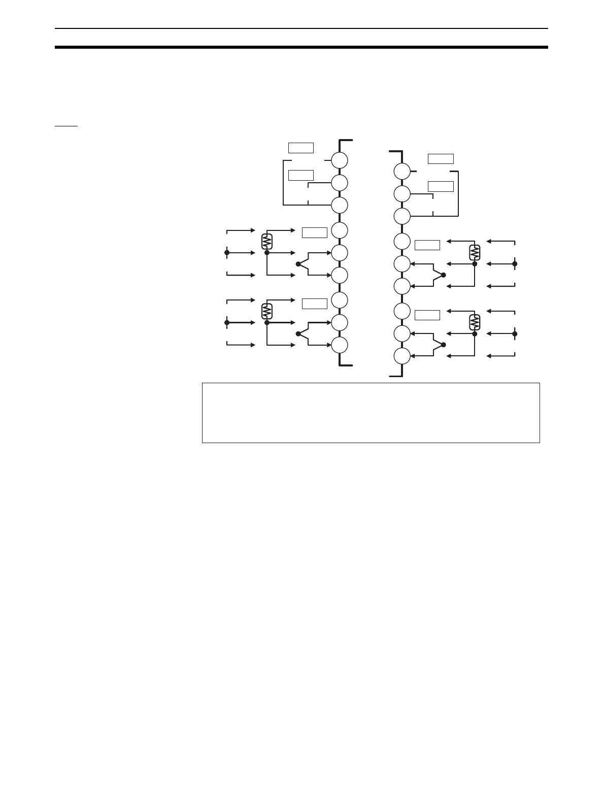
2-2 Wiring Terminals
2-2-1 Terminal Arrangement
TC4
A1
A2
A3
B1
B2
B3
B4
mA
V
B5
B6
B
A
B
ch2
B7
mA
V
B8
B9
B
A
B
ch1
A4
mA
V
A5
A6
B
A
B
ch4
A7
mA
V
A8
A9
B
A
B
ch3
• Terminals A10 and B10 are not used on models with screw-less clamp terminals.
Do not connect anything to these terminals.
• A G3ZA connector is located on the bottom of the Unit.
• When wiring voltage inputs, be sure to wire the correct terminals. Incorrect wiring
may cause the EJ1 to fail.
Pulse voltage outputs
12 VDC
12 VDC
12 VDC
12 VDC
Analog inputs
Platinum
resistance
thermometer
inputs
Thermocou-
ple inputs
Infrared ther-
mosensor
OUT2
OUT1
OUT4
OUT3
+
+
−
+
+
−
+
+
−
−
+
+
−
+
+
−
+
+
−
−
+
+
−
+
+
−