17
Wiring Terminals Section 2-2
TC2
HFU
COM
A4
A5
A6
A7
A8
A9
EV1
EV2
B1
B2
B3
B4
mA
V
B5
B6
B
A
B
ch2
B7
mA
V
B8
B9
B
A
B
ch1
CT1
CT2
A1
A3
A2
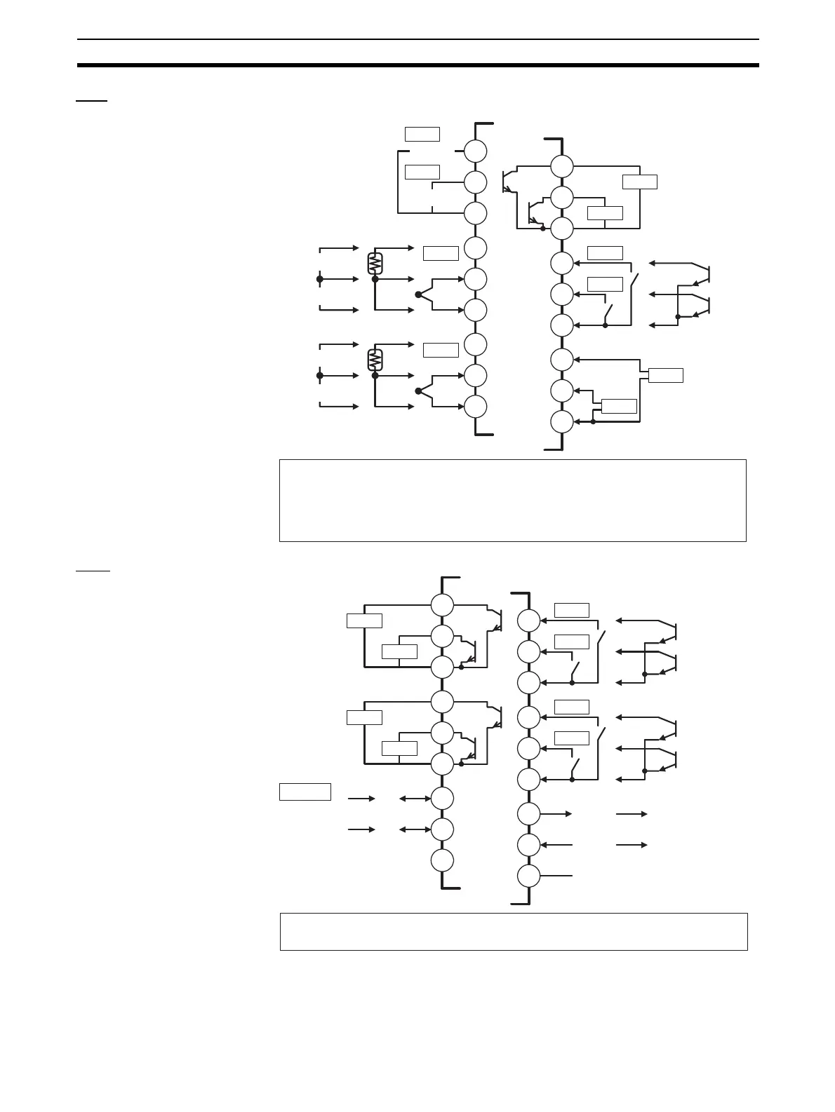
• Terminals A10 and B10 are not used on models with screw-less clamp terminals.
Do not connect anything to these terminals.
• A G3ZA connector is located on the bottom of the Unit.
• When wiring voltage inputs, be sure to wire the correct terminals. Incorrect wiring
may cause the EJ1 to fail.
Pulse voltage outputs
12 VDC
Analog inputs
Platinum
resistance
thermometer
inputs
Thermocou-
ple inputs
Infrared ther-
mosensor
Contact input
Non-contact input
12 VDC
OUT2
OUT1
OUT4
OUT3
+
+
−
−
−
−
−
−
+
+
+
+
+
+
+
+
A1
A4
A5
A6
A7
A8
A9
A3
A2
EV1
EV2
RS-232C RS-422
RS-422 RS-485
EV3
EV4
SD
RD
SG
B1
B2
B3
B4
B5
B6
B7
B8
B9
Contact input
Non-contact input
SUB4
SUB3
SUB2
SUB1
• Terminals A10 and B10 are not used on models with screw-less clamp terminals.
Do not connect anything to these terminals.
Port C
DO NOT USE
DO NOT USE
B (+)
A (−)
RDB (+)
RDA (−)
SDB (+)
SDA (−)
COM
COM
+
+
−
+
+
−