78
Setting Control Specifications Section 4-3
4-3-9 Disturbance Overshoot Adjustment Function
The Disturbance Overshoot Adjustment Function adjusts the control wave-
form when an external disturbance impacts the system.
• When using this function, set the Disturbance Overshoot Adjustment
Function parameter to 1 (Enabled).
• The disturbance response waveform can be adjusted with the Distur-
bance Gain and Disturbance Time Constant parameters.
Note (1) This parameter can be set only when operation is stopped.
(2) The decimal point position is determined by the sensor selection. With
analog inputs, the decimal point position is determined by the Decimal
Point Position parameter setting. In this case, however, the 0 (****) deci-
mal point position setting will be treated as setting 1 (***.*).
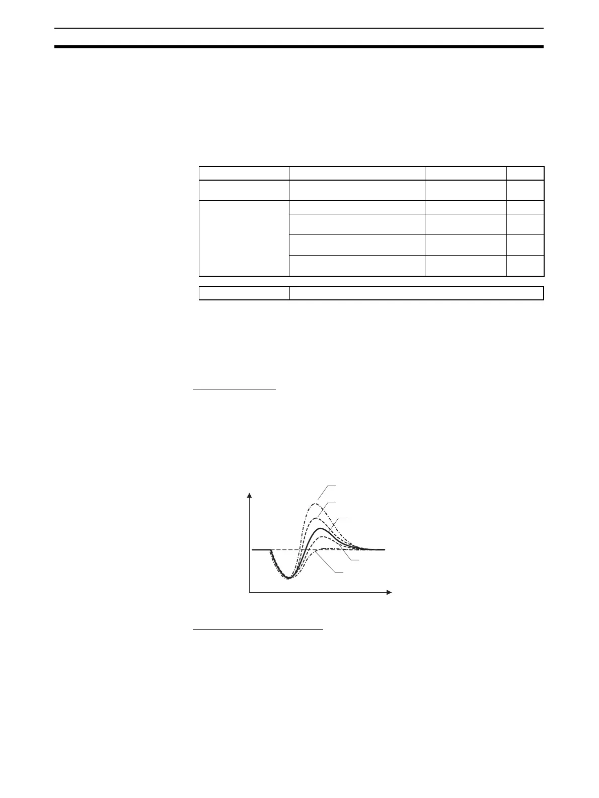
■ Disturbance Gain
• Overshooting due to a disturbance can be suppressed more by increasing
the Disturbance Gain.
• Overshooting due to a disturbance can be increased by decreasing the
Disturbance Gain.
• If the Disturbance Gain is set to 0, the Disturbance Overshoot Adjustment
Function will not operate.
■ Disturbance Time Constant
The recovery time from the disturbance can be made longer by increasing the
Disturbance Time Constant. The Disturbance Time Constant is normally left
at its default setting of 1. Use this parameter for fine-tuning when adjusting the
Disturbance Gain alone is not sufficient.
Variable type Parameter name Setting range Default
E5/A5 (See note 1.)
Disturbance Overshoot Adjustment
Function (Common)
0: Disabled
1: Enabled
0
D5/95
Disturbance Gain (Channel) −1.00 to 1.00
0.65
Disturbance Time Constant
(Channel)
0.01 to 99.99 s
1.00
Disturbance Rectification Band
(Channel)
0 to 9999 EU
(See note 2.)
0
Disturbance Judgment Width
(Channel)
−1999 to 9999 EU
(See note 2.)
0
Conditions for use The control method must be set to 2-PID control.
0
SP
Temperature
Disturbance Gain = −1
Disturbance Gain = −0.5
Disturbance Gain = 0
Disturbance Gain = 0.5
Disturbance Gain = 1
Time