165
Determining Errors from Indicators
Section 7-2
7-2 Determining Errors from Indicators
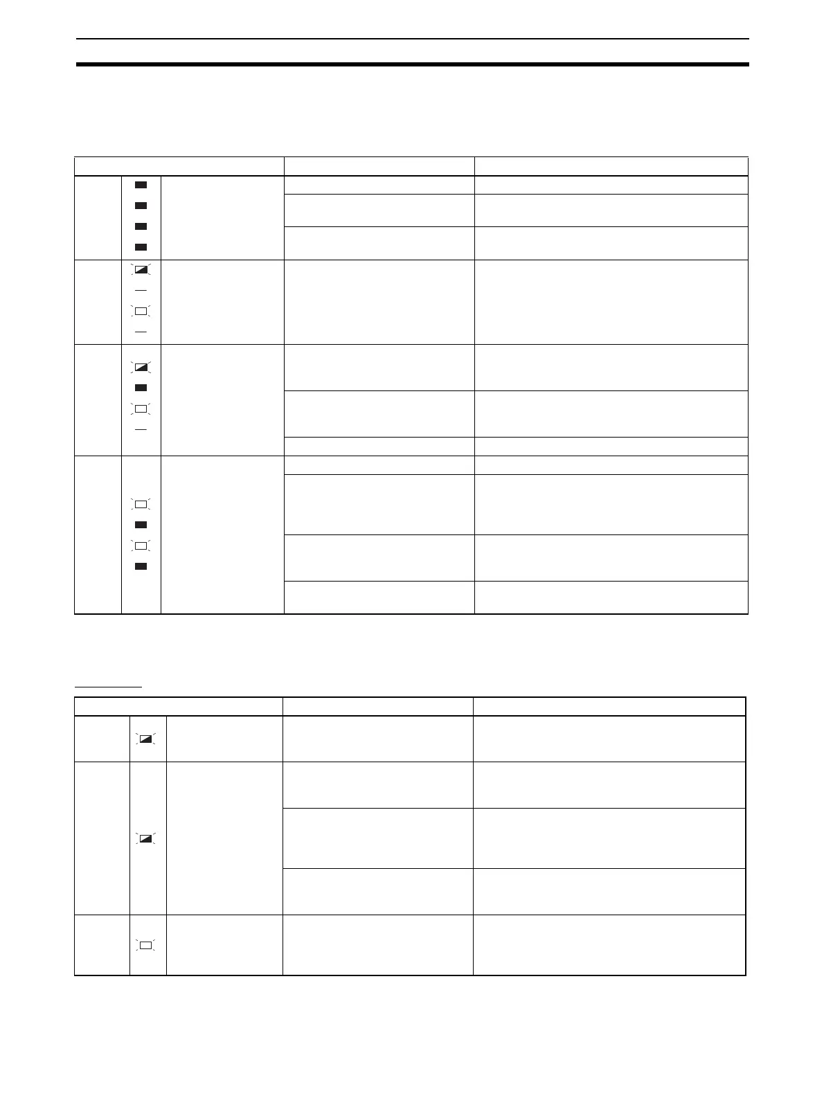
The following table shows indicator status, possible error causes, and coun-
termeasures.
In addition to the above, the status of the following indicators can be used to
determine the cause of and countermeasures for errors.
TC4/TC2
Status Possible causes Countermeasure
PWR
RUN
ERR
ALM
Not lit
Not lit
Not lit
Not lit
There is no power supply. Check to see if the Units are linked properly.
The power supply voltage is out-
side the allowable range.
Adjust the voltage to within the range.
The Unit is malfunctioning. Replace the Unit.
PWR
RUN
ERR
ALM
Green, flashing 0.5 s
---
Red, lit
---
The Unit is malfunctioning. Cycle the power supply. If the problem persists,
replace the Unit.
PWR
RUN
ERR
ALM
Green, flashing 1 s
Not lit
Red, lit
---
The settings data is corrupted. Send the Parameter Initialization operation com-
mand to initialize the parameters and then set
them again.
The Unit configuration informa-
tion is corrupted (Basic Units
only).
Send the Register Unit Configuration: Reset
operation command and then cycle the EJ1
power supply.
The Unit is malfunctioning. Replace the Unit.
PWR
RUN
ERR
ALM
Green, lit
Not lit
Red, lit
Not lit
A Unit is not connected correctly. Check Unit models and the order of connection.
The registered Unit configura-
tion does not match the actual
Unit configuration (Basic Units
only).
Restore the registered Unit configuration or re-
register the configuration.
The same unit number is set for
more than one connected G3ZA
(Basic Units only).
Correct the G3ZA unit number settings and then
cycle the power supply.
There is an error in a connected
G3ZA (Basic Units only).
Refer to the G3ZA User’s Manual (Cat. No.
Z200) and take the required countermeasures.
Status Possible causes Countermeasure
RUN Green, flashing
There is an error in a channel
that is currently running.
Read status to determine the channel that has
an error and then determine the cause from the
status of the ERR and ALM indicators.
ERR Red, flashing
There is an input error or a
remote SP input error.
Check the wiring for the input or remote SP
input to be sure it is wired correctly, not broken,
and not shorted. Also check the input type.
An error has occurred for which
the Operation During Error
(Selection B) parameter is set to
MV at PV Error or Stop control.
Read status to determine the nature of the error
and take appropriate measures.
An error has occurred in commu-
nications with a connected
G3ZA.
Check the connection to the G3ZA and take
appropriate measures.
ALM Red, lit
One of the following alarms has
occurred: heater burnout alarm,
heater short alarm, or heater
overcurrent alarm.
Read the Error Channel A Status, the Channel
Status, and the Channel Alarm Status to deter-
mine the channel with the alarm and the nature
of the alarm, and take appropriate measures.