199
Parameter List Appendix
Note The decimal point position is determined by the sensor selection. With analog inputs, the decimal point
position is determined by the Decimal Point Position parameter setting. In this case, however, the 0 (****)
decimal point position setting will be treated as a setting of 1 (***.*).
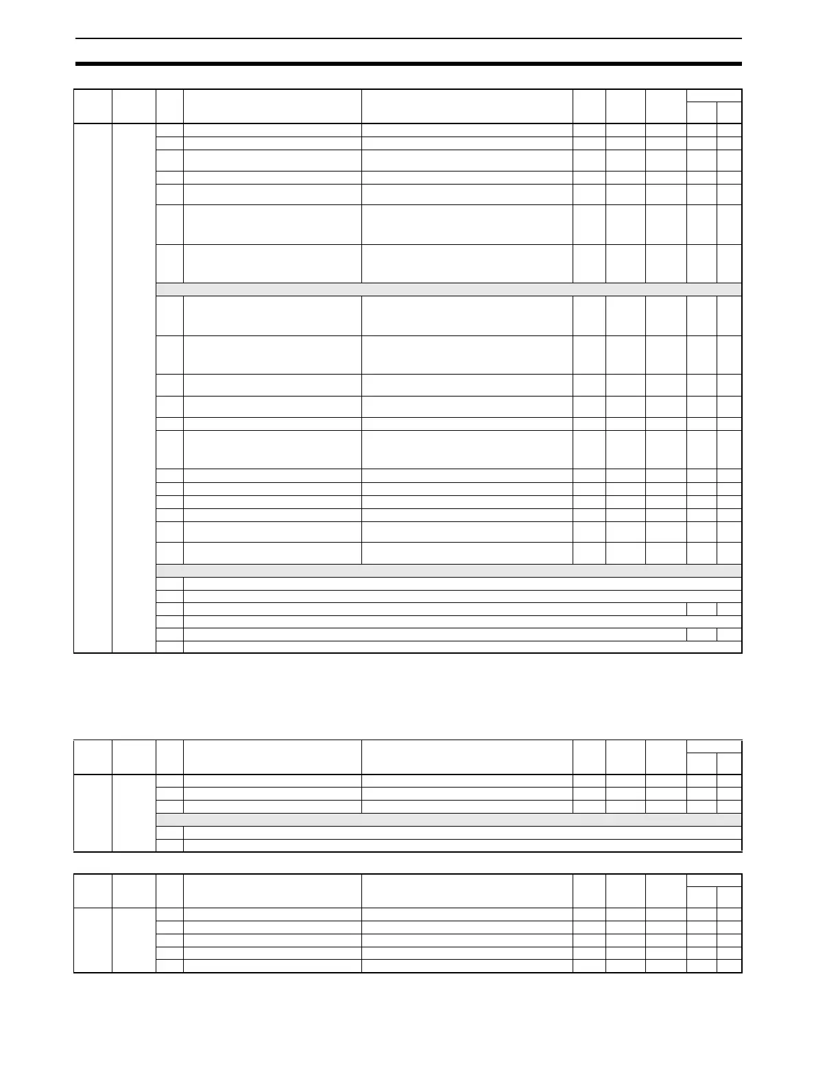
Variable
type
Category Add-
ress
Parameter name Setting (monitor) range Defau-
lt
Unit Attribut-
es
Target Unit
TC4/
TC2
HFU
D5 (95) Can be
changed
during
operation.
0100 Input Digital Filter - CH1 H' 00000000 to H' 0000270F (0.0 to 999.9) 0.0 Seconds ch ● ---
0101 Input Value 1 for Input Correction - CH1 H' FFFFF831 to H' 0000270F (−1999 to 9999) 0 EU ch ● ---
0102 Input Shift 1 - CH1 H' FFFFF831 to H' 0000270F (−1999 to 9999) 0 EU (See
note.)
ch ● ---
0103 Input Value 2 for Input Correction - CH1 H' FFFFF831 to H' 0000270F (−1999 to 9999) 1000 EU ch ● ---
0104 Input Shift 2 - CH1 H' FFFFF831 to H' 0000270F (−1999 to 9999) 0 EU (See
note.)
ch ● ---
0105 MV at PV Error - CH1
Standard Control: H' FFFFFFCE to H' 0000041A (−5.0 to 105.0) 0 % ch ● ---
Heating and Cooling Control: H' FFFFFBE6 to H' 0000041A (−105.0 to 105.0)
0106 MV at Stop - CH1
Standard Control: H' FFFFFFCE to H' 0000041A (−5.0 to 105.0) 0 % ch ● ---
Heating and Cooling Control: H' FFFFFBE6 to H' 0000041A (−105.0 to 105.0)
Not used.
0109 MV Upper Limit - CH1
Standard Control: H' FFFFFFCE to H' 0000041A (−5.0 to 105.0) 105.0 % ch ● ---
Heating and Cooling Control: H' 00000000 to H' 0000041A (−0.0 to 105.0)
010A MV Lower Limit - CH1
Standard Control: H' FFFFFFCE to H' 0000041A (−5.0 to 105.0) −105.0 % ch ● ---
Heating and Cooling Control: H' FFFFFBE6 to H' 00000000 (−105.0 to 0.0)
010B Hysteresis (Heating) - CH1 H' 00000001 to H' 0000270F (1 to 9999) 10 EU (See
note.)
ch ● ---
010C Hysteresis (Cooling) - CH1 H' 00000001 to H' 0000270F (1 to 9999) 10 EU (See
note.)
ch ● ---
010D Alpha - CH1 H' 00000000 to H' 00000064 (0.00 to 1.00) 0.65 --- ch ● ---
010E Manual MV - CH1
Standard Control: H' FFFFFFCE to H' 0000041A (−5.0 to 105.0) 0 % ch ● ---
Heating and Cooling Control: H' FFFFFBE6 to H' 0000041A (−105.0 to 105.0)
010F SP Upper Limit - CH1 H' FFFFF831 to H' 0000270F (−1999 to 9999) 9999 EU ch ● ---
0110 SP Lower Limit - CH1 H' FFFFF831 to H' 0000270F (−1999 to 9999) −1999 EU ch ● ---
0111 Disturbance Gain - CH1 H' FFFFFF9C to H' 00000064 (−1.00 to 1.00) 0.65 --- ch ● ---
0112 Disturbance Time Constant - CH1 H' 00000001 to H' 0000270F (0.01 to 99.99) 1.00 Seconds ch ● ---
0113 Disturbance Rectification Band - CH1 H' 00000000 to H' 0000270F (0 to 9999) 0 EU (See
note.)
ch ● ---
0114 Disturbance Judgment Width - CH1 H' FFFFF831 to H' 0000270F (−1999 to 9999) 0 EU (See
note.)
ch ● ---
Not used.
0200 Input Digital Filter - CH2 The rest are the same as channel 1.
···
···
0300 Input Digital Filter - CH3 TC4 ---
···
···
0400 Input Digital Filter - CH4 TC4 ---
···
···
Variable
type
Category Add-
ress
Parameter name Setting (monitor) range Defau-
lt
Unit Attribut-
es
Target Unit
TC4/
TC2
HFU
D6 (96) Can be
changed
during
operation.
0100 Heater Burnout 1 Detection H' 00000000 to H' 000003E8 (0.0 to 100.0) 0.0 A IO TC2 ---
0101 HS Alarm 1 H' 00000000 to H' 000003E8 (0.0 to 100.0) 100.0 A IO TC2 ---
0102 Heater Overcurrent 1 Detection H' 00000000 to H' 000003E8 (0.0 to 100.0) 100.0 A IO TC2 ---
Not used.
0200 Heater Burnout 2 Detection The rest are the same as from Heater Burnout Detection 1 to Heater Overcurrent Detection 1.
···
···
Variable
type
Category Add-
ress
Parameter name Setting (monitor) range Defau-
lt
Unit Attribut-
es
Target Unit
TC4/
TC2
HFU
D7 (97) Can be
changed
during
operation.
0004 Programless Upload Settings 4 0900 --- NUM --- ●
0005 Programless Upload Settings 5 0B00 --- NUM --- ●
0006 Programless Upload Settings 6 00FF --- NUM --- ●
···
···
···
···
···
···
···
···
012F Programless Upload Settings 303 00FF --- NUM --- ●