21
Wiring Terminals Section 2-2
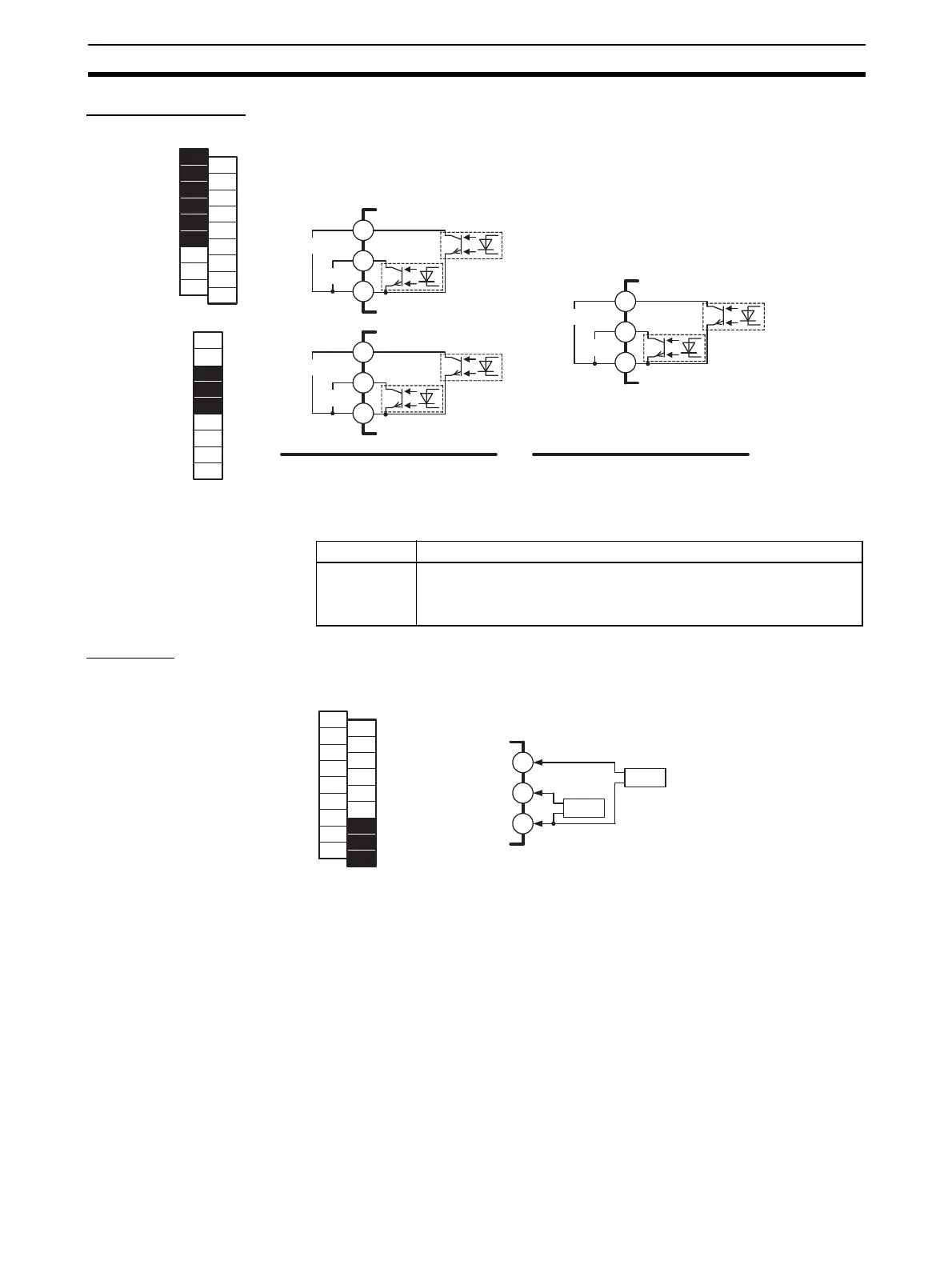
Auxiliary Outputs Auxiliary outputs are sent from pins B1 to B6 with the HFU, and from pins 3 to
5 with the EDU.
CT Inputs When the heater burnout (HB), heater overcurrent (OC), or heater short (HS)
alarm is to be used, connect a Current Transformer (CT) across terminals A8
and A9 or terminals A7 and A9 (no polarity) on the TC2.
• Use a E54-CT1 or E54-CT3 Current Transformer.
B1
B2
B3
SUB3
SUB4
B4
B5
B6
SUB1
SUB2
3
4
5
SUB1
SUB2
B1
B2
B3
B4
B5
B6
B7
B8
B9
A1
A2
A3
A4
A5
A6
A7
A8
A9
HFU
1
2
3
4
5
6
7
8
9
EDU
HFU
COM
COM
COM
EDU
Output type Specifications
Transistor
outputs
Max. operating voltage: 30 VDC
Max. load current: 50 mA
Residual voltage: 1.5 V max., leakage current: 0.4 mA max.
A7
A8
A9
CT1
CT2
B1
B2
B3
B4
B5
B6
B7
B8
B9
A1
A2
A3
A4
A5
A6
A7
A8
A9
TC2