114
Chapter4 Installation Conditions
F3SJ-A
User’s Manual
Wiring/Installation
•Tm = Response time of the machine (s)
•Ts = F3SJ's response time from ON to OFF (s)
[Example]
If Tm = 0.05s and Ts = 0.01s:
S = 1,600mm/s x (0.05s + 0.01s) + 850mm
= 946mm
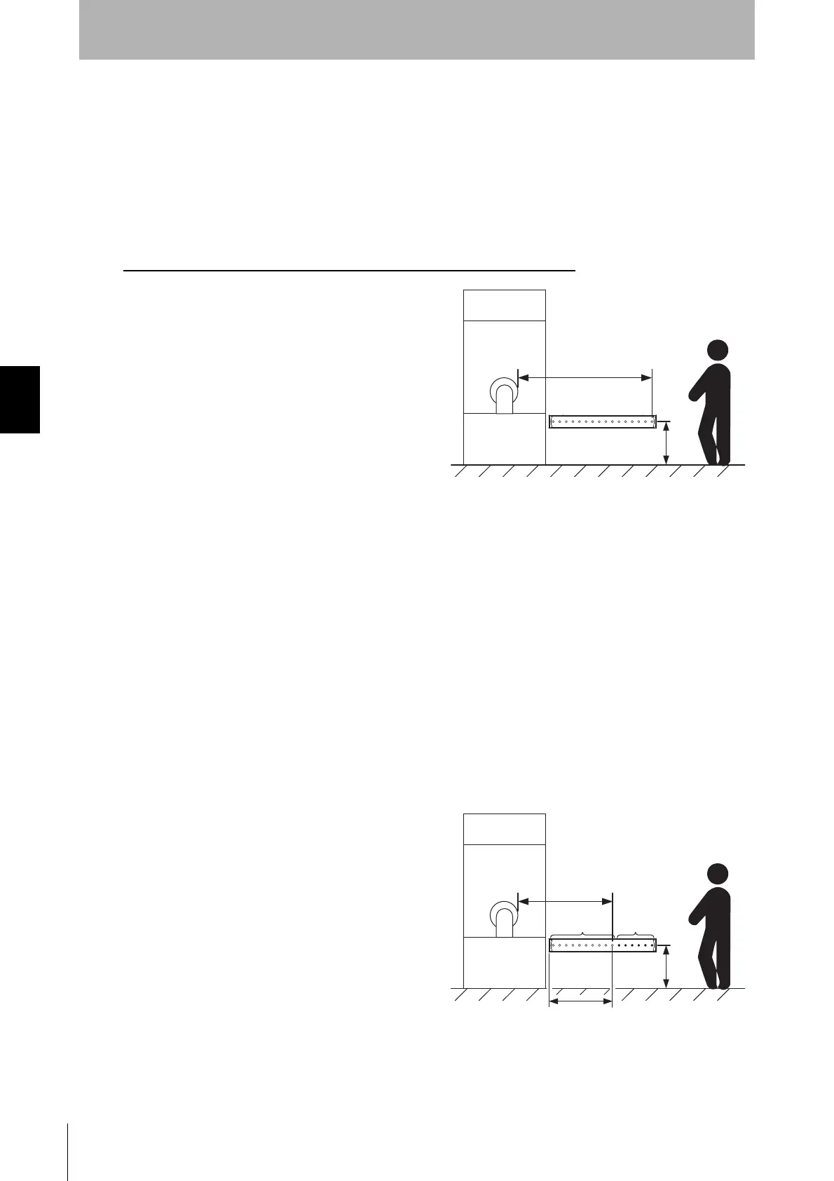
In case of horizontal approach of a human body to F3SJ's detection zone
Use K = 1,600mm/s and C = (1200 - 0.4 x H) in
formula (1) for calculation.Note that C must not be
less than 850mm.
S = 1,600mm/s x (Tm + Ts) + 1200 - 0.4 x H
•S = Safety distance (mm)
•Tm = Machine's response time (s)
•Ts = Response time of F3SJ from ON to OFF (s)
•H = Installation height (mm)
Note that H must satisfy:
1000 >= H >= 15 (d - 50mm)
Also, you must include a hazardous condition under which a person may go through under a detection
zone carelessly if it exceeds 300mm (200mm for other purpose than industrial use) into risk
assessment.
[Calculation example]
When Tm = 0.05s, Ts = 0.01s, and d = 14mm:
S = 1,600mm/s x (0.05s + 0.01s) + 1200 - 0.4 x 500mm
= 1096mm
When a warning zone is configured as in the figure, you must calculate L, a distance form an end of
casing to a detection zone, using a formula below:
L = (Total number of F3SJ beams - number of warning zone beams - 1) x P + 10
•P: Beam Gap (mm)
F3SJ-AN14 . . . 9mm
F3SJ-AN20 . . . 15mm
F3SJ-AN25 . . . 20mm
F3SJ-AN30 . . . 25mm
F3SJ-AN55 . . . 50mm
For total number of F3SJ beams, see "Model
Name List/Response Times p.17 ".
*
Safety distance (S)
Hazard
H
Safety
distance (S)
Hazard
Distance L from casing end
to detection zone
Detection
zone
Warning
zone

 Loading...


