166
Chapter5 Input/Output Circuit
F3SJ-A
User’s Manual
Input/Output Circuit and Applications
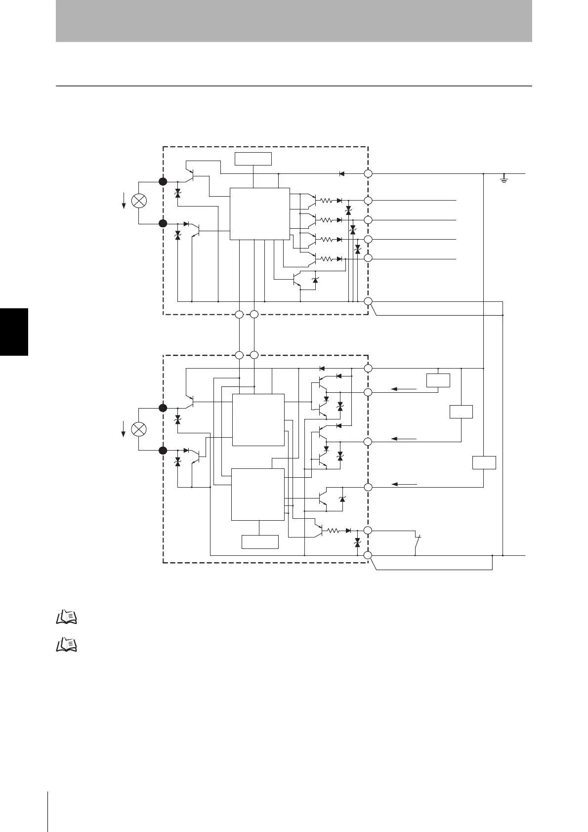
Input/Output Circuit
The numbers in white circles indicate the connector's pin numbers.
The black circles indicate connectors for series connection.
The words in brackets [ ] indicate the signal name for muting system.
For details about wiring, see the following sections.
When not using the muting function, see p.27
When using muting function, see p.40
+24V
0V
DC
5
10
5
10
2
1
8
1
2
3
1
4
7
8
5
5
6
6
3
4
7
Emitter
Main Circuit
Indication
Receiver
Main Circuit 2
Communication line (-)
Pink
Grey
Grey
Pink
Communication line (+)
External indicator output 1
External indicator output 2
Brown
Brown
Test input
White
Interlock selection input
[Muting input 1]
Red
[Muting input 2]
Reset input
Yellow
Yellow
Blue
Shield
Shield
Blue
Brown
Blue
Brown
Auxiliary output 1
Safety output 1
Red
External device monitoring input
White
Safety output 2
Blue
Load
Load
Load
Indication
Receiver
Main Circuit 1
Auxiliary output 2
* Green for the single-ended cable F39-JCA.
Black*
Black*

 Loading...


