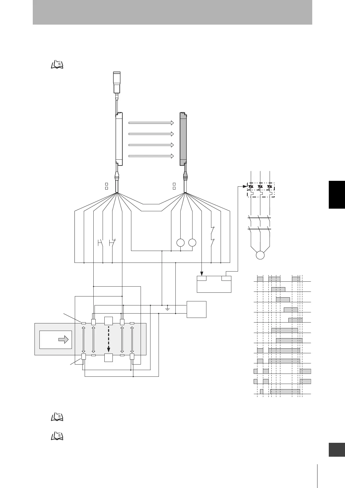
F3S J
KM1
KM2
S1
S2
M
KM1
KM2
OUT
PLC
IN
KM3
+DC24 V
0 V
E1
A1
B1
A
2
B2
KM1 KM2
Workpiece
(NPN output)
Reflector
Muting sensor
Unblocked
Blocked
Muting input 1
Muting input 2
F3SJ Safety output
A1 Safety output
B1 Safety output
A2 Safety output
B2 Safety output
KM1,KM2 N.O. contact
KM1,KM2 N.C. contact
PLC input (*2)
PLC output
Emitter Receiver
Muting lamp
(external indicator)
- Auto reset mode
- Using external device monitoring function
S1 :External test switch
S2 :Lockout reset switch
KM1, KM2 :Safety relay with forcibly-guided contact (G7SA) or
magnetic contactor
KM3 :Solid state contactor (G3J)
M :3-phase motor
E1 :24VDC power supply (S82K)
PLC :Programmable controller
(Used for monitoring -- not related to safety system)
A1,B1,A2,B2 : Muting sensor (Retro-reflective photoelectric
sensor (E3Z-R61))
Communication
line (+) (Grey)
Communication
line (-) (Pink)
Shield
0V (Blue)
Muting input 2 (Red)
Muting input 1 (White)
+24V (Brown)
+24V (Brown)
External device monitoring input (Red)
Safety
output 2 (White)
0V (Blue)
Shield
Reset input (Yellow)
Auxiliary output 1 (Yellow)
(connect to 24V if a switch is not required)
(connect to 0V if a switch is not required)
Two-wire type sensor cannot be used.
F39-JC A-L F39-JC A-D
F39-JD A-L F39-JD A-D
Test input (Black)
Safety
output 1 (Black)
*1
*1
*1 Green for the single-ended cable F39-JCA
*2 Output operation mode of auxiliary output 1 is "safety output information/reverse enabled" (initial setting)

 Loading...


