41
F3SJ-A
User’s Manual
Chapter2 Muting System
System Configuration and Functions
E
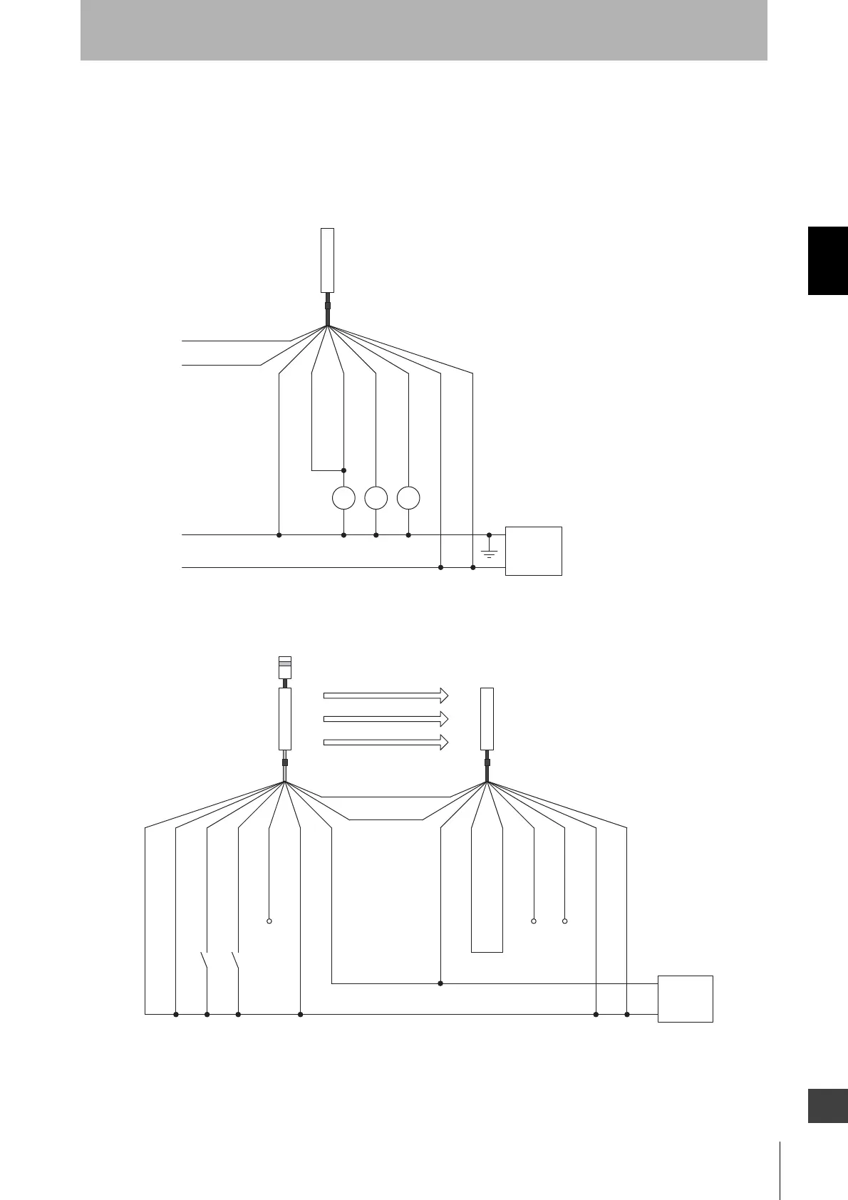
Wiring When External Device Monitoring Function Is Not Required
1.Disabling external device monitoring function by the setting tool
Or
2.The external device monitoring function is disabled by connecting auxiliary output 1 and external
device monitoring input as shown below, when auxiliary output 1 settings have not been changed
(output operation mode is "safety output information" and reverse output mode is "enabled").
Ref.: Minimum Wiring Required to Check the Operation of the F3SJ When Using the
Muting Function
(Wiring that does not use the external device monitoring function)
*1
K1 K2K3
+24V DC
0V
K1, K2
K3
: Relay or other device that controls
hazardous parts of the machine
: Load or PLC, etc. (for monitoring)
*1 F3SJ can operate even if K3 is not connected.
If K3 is not required, connect auxiliary output 1 to
external device monitoring input only.
*2 Green for the single-ended cable F39-JCA.
Receiver
(Grey) Communication line (+)
(Pink) Communication line (-)
0V(Blue)
Power
supply
Shield
24V(Brown)
External device
monitoring input(Red)
Auxiliary output 1(Yellow)
Safety output 2(White)
Safety output 1(Black)
*2
Open
Open
Open
A1B1
*1*1
M1*1 *2
+24V DC
0V
A1
: Contact by muting sensor A1
B1 : Contact by muting sensor B1
M1 : Muting lamp
*1
When the muting function's operation check is not performed, it can work if this is open.
*2 Connect either the emitter or receiver to the muting lamp.
*3
Two-wire type sensor cannot be used.
*4 Green for the single-ended cable F39-JCA.
Emitter
Receiver
(Grey) Communication line (+)
(Pink) Communication line (-)
0V(Blue)
0V(Blue)
Power
supply
Shield
Shield
Reset input(Yellow)
24V(Brown)
24V(Brown)
External device
monitoring input(Red)
Auxiliary output 1(Yellow)
Safety output 2(White)
Muting input 1 (White)
Muting input 2 (Red)
33
*
*
Test input(Black)
Safety output 1(Black)
*4
*4

 Loading...


