171
F3SJ-A
User’s Manual
Chapter5 Wiring Examples
Input/Output Circuit and Applications
E
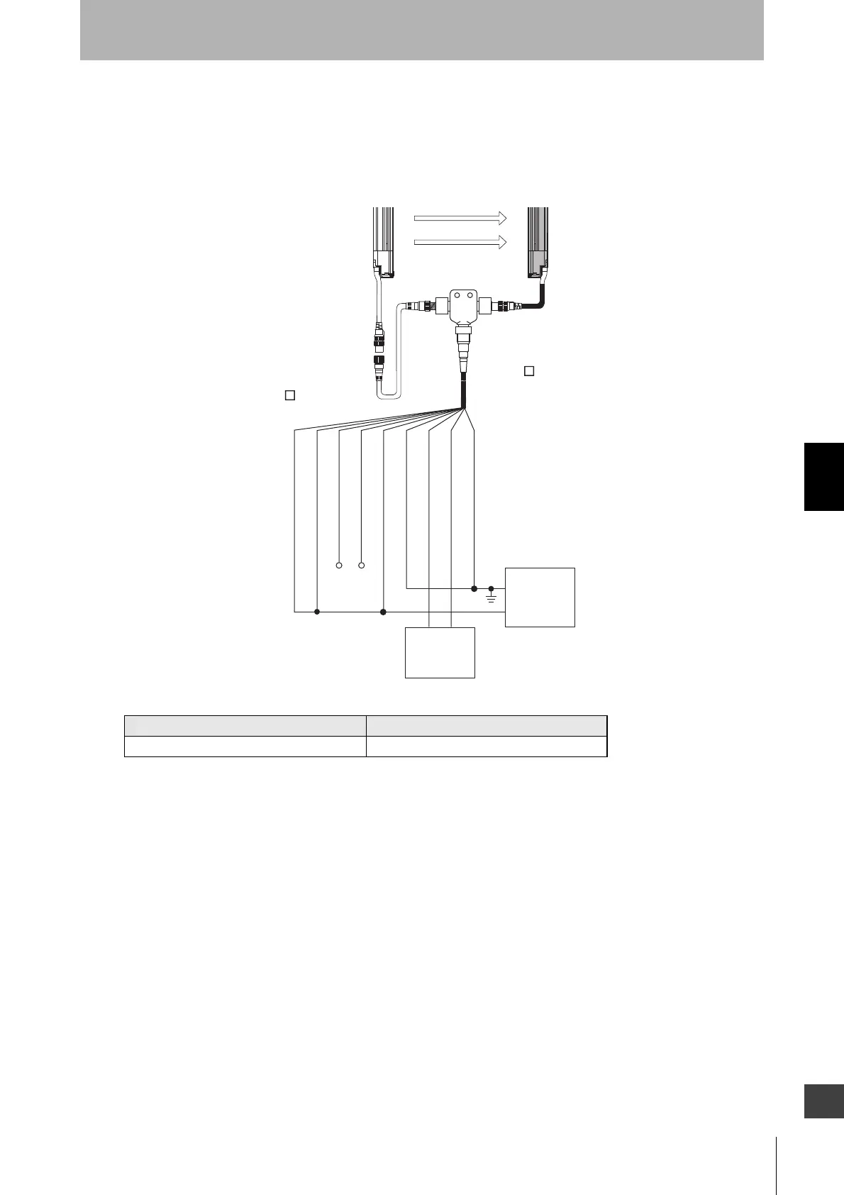
Using a reduced wiring connector
•A combination of a cable for reduced wiring (F39-JDBA) and a reduced wiring connector (F39-CN5)
can be used for a reduced wiring system.
An example of a control unit connectable to F3SJ
Safety Controller Model
Safety Relay Unit G9SA-301-P
+24V DC
0V
Power
supply
F3SJ
Receiver
F3SJ
Emitter
Reduced Wiring
Connector
F39-CN5
Cable with connector
on one end
F39-JD A-D (black)
Cable with connectors
on both ends
F39-JD B-L (grey)
Safety
controllers,
etc.
0V (Blue)
Shield
+24V (Brown)
Test input (Red)
Reset input (Yellow)
Safety output 1 (Black)
Safety output 2 (White)
Communication line (+) (Grey)
Communication line (-) (Pink)

 Loading...


