additional configuration.
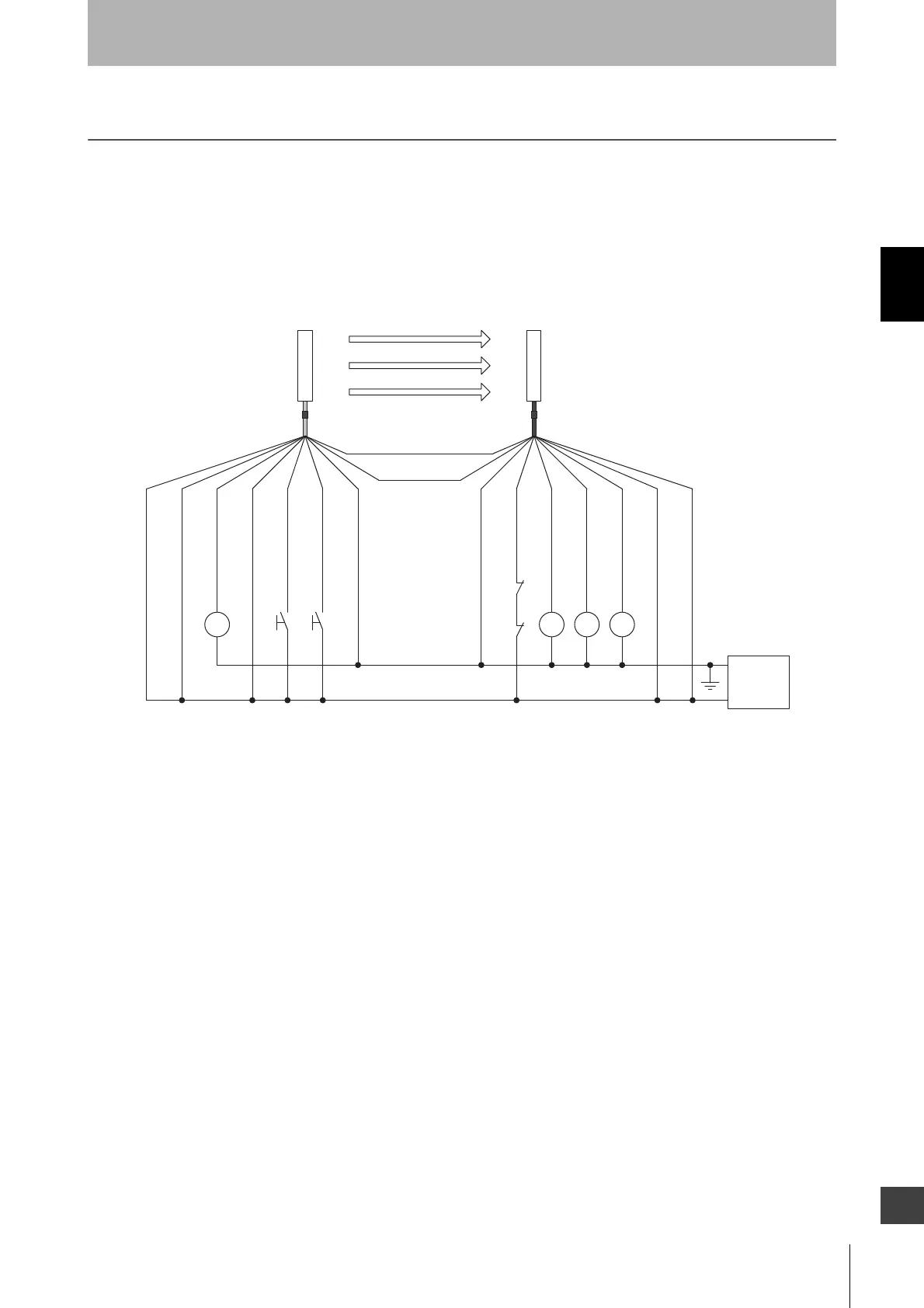
K1
K2
S1 S 2
*1
*1
*2
K1
K2
K
3
+24V D C
0V
*2
K4
Interlock selection input (White)
S1
S2
K1, K2
K3, K4
: External test switch (connect to 24V if a switch is not required)
: Interlock/lockout reset switch
: Relay or other device that controls hazardous parts of the machine
: Load or PLC, etc. (for monitoring)
Emitter
Receiver
(Grey) Communication line (+)
(Pink)
Communication line (-)
0V(Blue)
0V(Blue)
Power
supply
Shield
Shield
Reset input(Yellow)
24V(Brown)
24V(Brown)
External device monitoring input
(Red)
Auxiliary output 1(Yellow)
Safety output 2(White)
Auxiliary output 2(Red)
Test input(Black)
Safety output 1(Black)
*3 *3
*1 Use a switch for micro loads (Input specifications: 5V, 1mA)
*2 F3SJ can operate even if K3 and K4 are not connected
*3 Green for the single-ended cable F39-JCA

 Loading...


