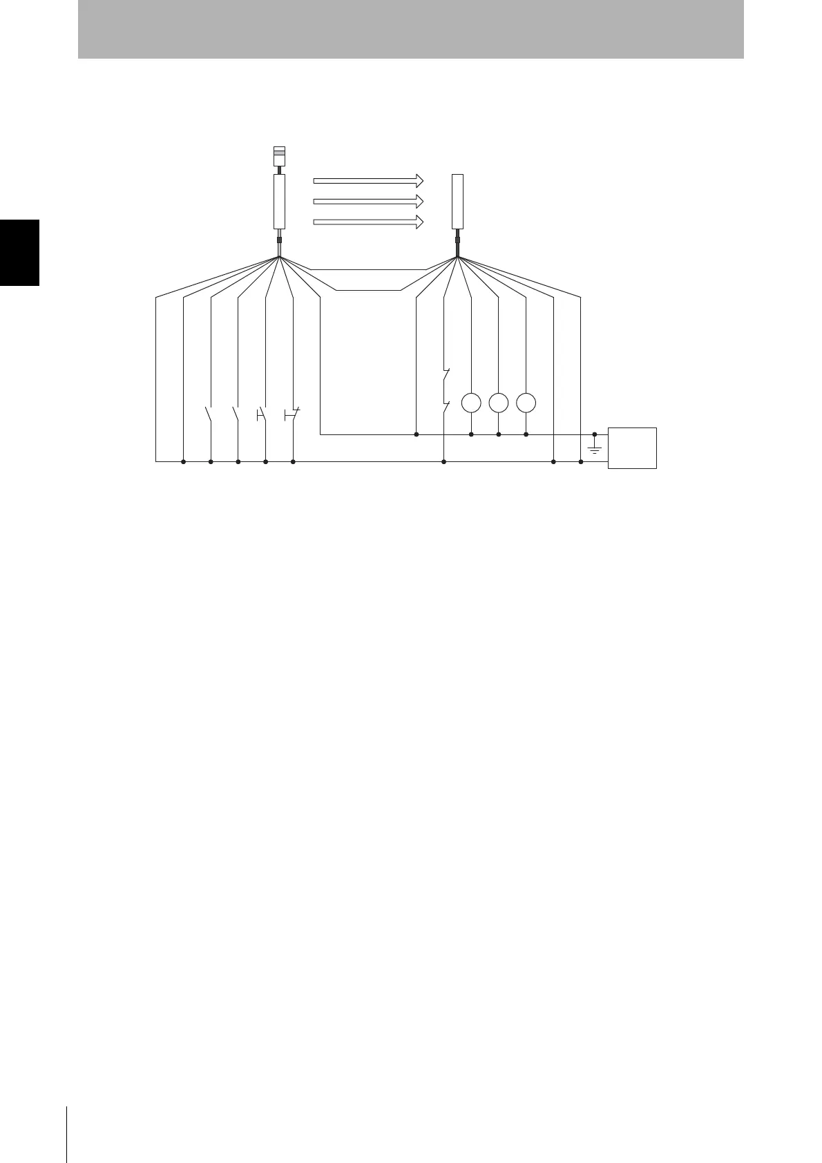
K1
K2
S1
*1
*1 *2
S2
A1B1
M1 *4
*3 *4
K1 K2K3
+24V DC
0V
Emitter
Receiver
(Grey) Communication line (+)
(Pink) Communication
line (-)
0V(Blue)
0V(Blue)
Power
supply
Shield
Shield
Reset input(Yellow)
24V(Brown)
24V(Brown)
External device
monitoring input(Red)
Auxiliary output 1(Yellow)
Safety output 2(White)
Muting input 1 (White)
Muting input 2 (Red)
S1 : External test switch (connect to 24V if a switch is not required)
S2 : Lockout reset switch (connect to 0V if a switch is not required)
A
1 : Contact by muting sensor A1
B1 : Contact by muting sensor B1
K1,K2 : Relay or other device that controls hazardous parts of the machine
M1 : Muting lamp
K3
:
Load or PLC, etc. (for monitoring)
*4
*1 Use a switch for small loads (input specifications: 5V, 1mA)
*2 Can work as an interlock reset switch when interlock function is used. (Configuration by the setting tool is required)
*3 F3SJ operates even when K3 is not connected.
*4 Connect a muting lamp to either of external indicator output or auxiliary output 1 of an emitter or a receiver.
To connect a muting lamp to the auxiliary output 1, setting must be changed by the setting tool.
*
*
Two-wire type sensor cannot be used.
5
*
Test input(Black)
Safety output 1(Black)
*6
*6
*6 Green for the single-ended cable F39-JCA.

 Loading...


