3 - 5
3 Specifications
OMNUC G5-series (Pulse-train Input Type) AC Servomotors and Servo Drives User’s Manual
3-1 Servo Drive Specifications
3
3-1-2 Characteristics
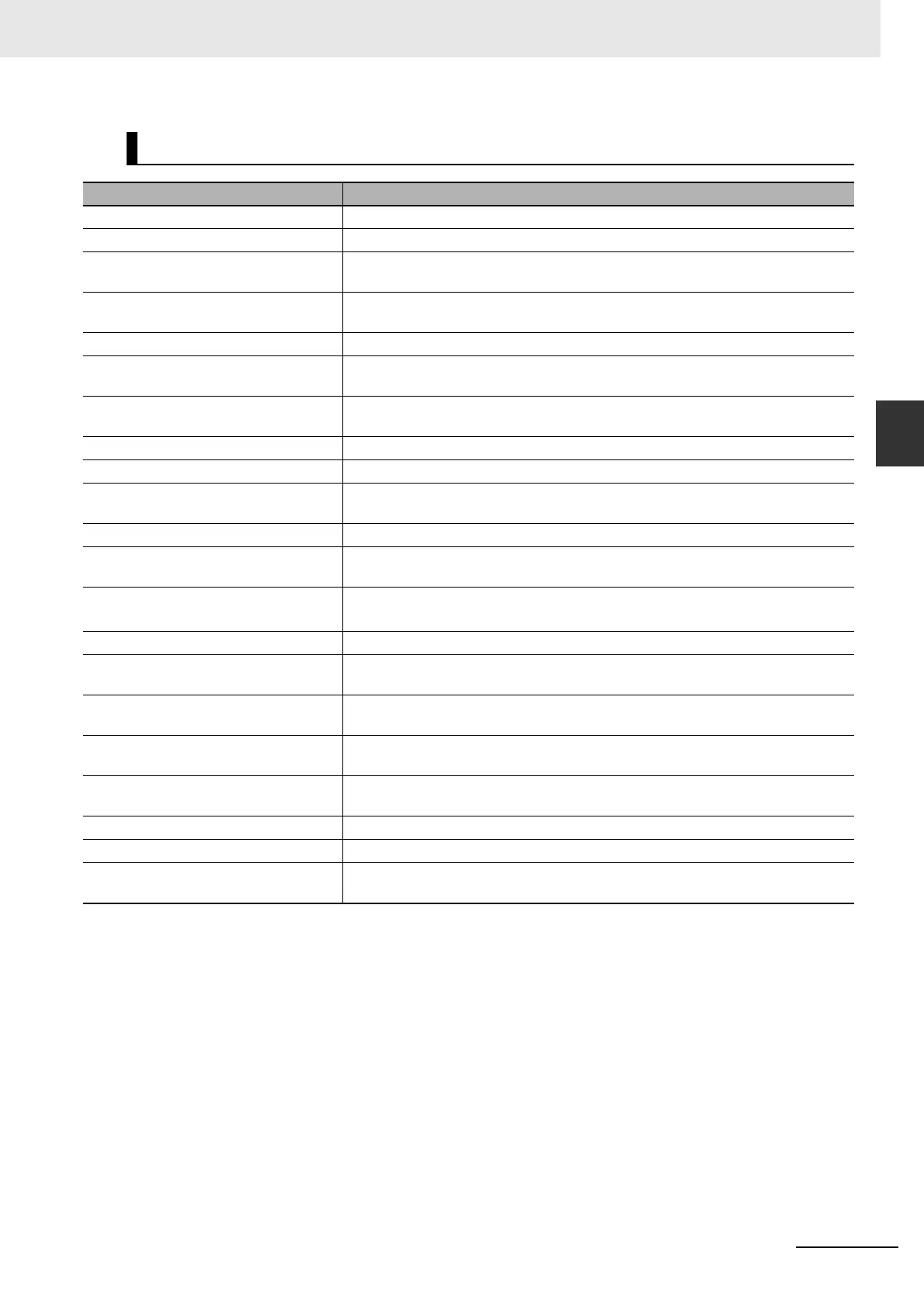
Protective Functions
Error detected Description
Control Power Supply Undervoltage The DC voltage in the control power supply dropped below the specified value.
Overvoltage The DC voltage in the main circuit power supply exceeded the specified value.
Main Power Supply Undervoltage The DC voltage in the main circuit power supply dropped below the specified
value.
Overcurrent Overcurrent flowed through the IGBT. The Servomotor power cable is ground-
faulted or short-circuited.
Servo Drive Overheat The temperature of the Servo Drive radiator exceeded the specified value.
Overload Operation was performed with a significantly overrated torque for a few seconds
to several tens of seconds.
Regeneration Overload The regenerative energy exceeded the regeneration absorption capacity of the
Regeneration Resistor.
Encoder Communications Error The encoder cable was disconnected.
Encoder Communications Data Error The Servo Drive cannot establish communications with the encoder.
Error Counter Overflow The number of accumulated pulses in the error counter exceeded the value set in
Error Counter Overflow Level (Pn014).
Overspeed The Servomotor rotation speed exceeded the maximum allowable speed.
Electronic Gear Setting Error The settings of the Electronic Gear Ratio (Pn009 to Pn010, Pn500 to Pn503) are
not appropriate.
Error Counter Overflow The error counter value obtained with reference to the encoder pulses exceeded
2
29
(536,870,912).
Interface I/O Setting Error An error was detected in the interface I/O signal.
Overrun Limit Error The Servomotor exceeded the allowable operating range set in Overrun Limit
Setting (Pn514) with respect to the position command input.
Parameter Error Data in the Parameter Save Area was corrupted when the power supply was
turned ON and data was read from the EEPROM.
Parameters Destruction The checksum did not match when the power supply was turned ON and data
was read from the EEPROM.
Drive Prohibition Input Error Both the Forward Drive Prohibition Input and Reverse Drive Prohibition Input
signals turned OFF.
Encoder Phase-Z Error A missed phase-Z pulse was detected.
Encoder CS Signal Error A logic error was detected in the CS signal.
Motor Non-conformity The combination of the Servomotor with the Servo Drive is not appropriate.
The encoder is not connected when the power supply is turned ON.
 Loading...


