21
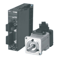
OMNUC G5-series (Pulse-train Input Type) AC Servomotors and Servo Drives User’s Manual
CONTENTS
2-4 External and Mounting Dimensions .................................................................................... 2-22
2-4-1 Servo Drive Dimensions ........................................................................................................... 2-22
2-4-2 Servomotor Dimensions ........................................................................................................... 2-31
2-4-3 Combinations of Servomotors and Decelerators...................................................................... 2-40
2-4-4 Decelerator Dimensions ........................................................................................................... 2-42
2-4-5 External Regeneration Resistor Dimensions............................................................................ 2-56
2-4-6 Reactor Dimensions ................................................................................................................. 2-57
2-4-7 Mounting Bracket (L-brackets for Rack Mounting) Dimensions................................................ 2-61
Section 3 Specifications
3-1 Servo Drive Specifications ..................................................................................................... 3-2
3-1-1 General Specifications................................................................................................................ 3-2
3-1-2 Characteristics............................................................................................................................ 3-3
3-1-3 Main Circuit and Motor Connections........................................................................................... 3-6
3-1-4 Control I/O Connector Specifications (CN1)............................................................................... 3-9
3-1-5 Control Input Circuits................................................................................................................ 3-15
3-1-6 Control Input Details................................................................................................................. 3-17
3-1-7 Control Output Circuits ............................................................................................................. 3-27
3-1-8 Control Output Details .............................................................................................................. 3-28
3-1-9 Encoder Connector Specifications (CN2)................................................................................. 3-32
3-1-10 Analog Monitor Connector Specifications (CN5) ...................................................................... 3-33
3-1-11 USB Connector Specifications (CN7)....................................................................................... 3-34
3-2 Overload Characteristics
(Electronic Thermal Function)3-35
3-2-1 Overload Characteristics Graphs.............................................................................................. 3-35
3-3 Servomotor Specifications ................................................................................................... 3-36
3-3-1 General Specifications.............................................................................................................. 3-36
3-3-2 Characteristics.......................................................................................................................... 3-37
3-3-3 Encoder Specifications............................................................................................................. 3-53
3-4 Decelerator Specifications ...................................................................................................3-54
3-4-1 Models and Specifications........................................................................................................ 3-54
3-5 Cable and Connector Specifications ................................................................................... 3-62
3-5-1 Resistance to Bending of Global Flexible Cable....................................................................... 3-62
3-5-2 Encoder Cable Specifications................................................................................................... 3-64
3-5-3 Motor Power Cable Specifications............................................................................................ 3-68
3-5-4 Connector Specifications.......................................................................................................... 3-80
3-5-5 Analog Monitor Cable Specifications........................................................................................3-83
3-5-6 Control Cable Specifications..................................................................................................... 3-84
3-6 Servo Relay Unit and Cable Specifications......................................................................... 3-96
3-6-1 Servo Relay Unit Specifications................................................................................................ 3-96
3-6-2 Servo Drive Relay Unit Cable Specifications.......................................................................... 3-108
3-6-3 Position Control Unit Relay Unit Cable Specifications............................................................ 3-111
3-7 External Regeneration Resistor Specifications................................................................ 3-122
3-7-1 External Regeneration Resistor Specifications ...................................................................... 3-122
3-8 Reactor Specifications........................................................................................................ 3-124
Section 4 System Design
4-1 Installation Conditions............................................................................................................ 4-2
4-1-1 Servo Drive Installation Conditions............................................................................................. 4-2
4-1-2 Servomotor Installation Conditions............................................................................................. 4-3
4-1-3 Decelerator Installation Conditions............................................................................................. 4-6
4-2 Wiring ..................................................................................................................................... 4-10
4-2-1 Peripheral Equipment Connection Examples ........................................................................... 4-10
4-2-2 Main Circuit and Motor Connections.........................................................................................4-14
 Loading...


