Appendices
A - 12
OMNUC G5-series (Pulse-train Input Type) AC Servomotors and Servo Drives User’s Manual
005
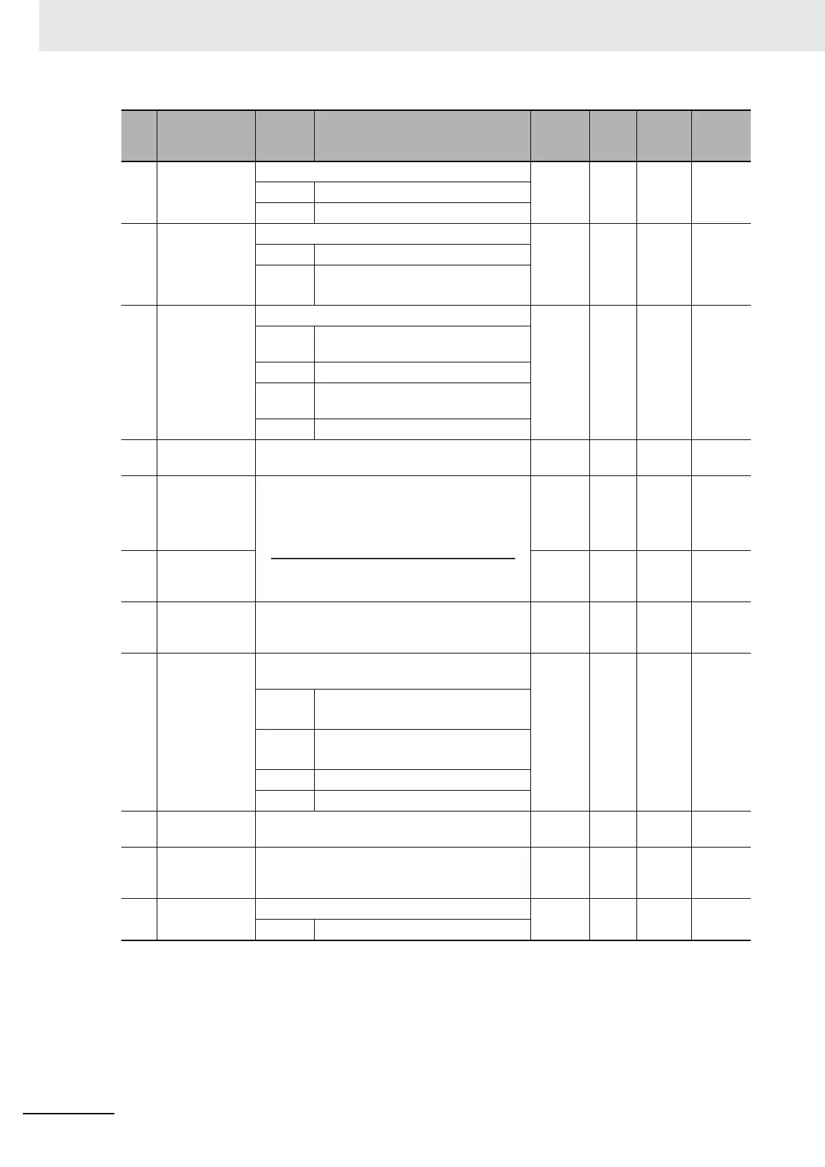
Command Pulse
Input Selection
Select the command pulse input mode. 0 – 0 to 1
Required
0 Photocoupler input
1 Input for line driver only
006 Command
Pulse Rotation
Direction
Switching
Selection
Select the command pulse count direction. 0 – 0 to 1
Required
0 Forward direction
1 Reverse direction
007 Command
Pulse Mode
Selection
Set the command pulse mode. 1 – 0 to 3
Required
0 90° phase difference (A/B) signal
input
1 Forward pulse/Reverse pulse
2 90° phase difference (A/B) signal
input
3 Feed pulse/Forward or reverse signal
008 Electronic Gear
Integer Setting
Set the number of command pulses per motor
rotation.
10,000
Pulse
0 to 2
20
Required
009 Electronic Gear
Ratio
Numerator 1
Set the electronic gear ratio.
If Pn009 = 0, the encoder resolution is set in the
numerator.
0–
0 to 2
30
–
010 Electronic Gear
Ratio
Denominator
10,000 –
1 to 2
30
–
011 Encoder
Dividing
Numerator
Set the number of output pulses per motor
rotation for phases A and B.
2,500 P/r 1 to
262,144
Required
012 Encoder Output
Direction
Switching
Selection
Select the combination of the phase-B logic and
the output source for pulse regeneration output.
0 – 0 to 1
Required
0 Phase-B logic: Not reversed
Output source: Encoder
1 Phase-B logic: Reversed
Output source: Encoder
2 Reserved (Do not set.)
3 Reserved (Do not set.)
013 No. 1 Torque
Limit
Set the first output torque limit of the
Servomotor.
500 % 0 to
500
–
014 Error Counter
Overflow Level
Set the range of the error counter overflow level.
Detection of error counter overflow level error is
disabled if the set value is 0.
10,0000
Command
unit
0 to 2
27
–
015 Reserved Do not set. 1 – 1 –
1 Use as incremental encoder.
Pn
No.
Name Setting Description
Default
setting
Unit
Setting
range
Cycle the
power
supply
Electronic Gear Ratio Denominator (Pn010)
Electronic Gear Ratio Numerator 1 (Pn009)

 Loading...


