2 - 37
2 Models and External Dimensions
OMNUC G5-series (Pulse-train Input Type) AC Servomotors and Servo Drives User’s Manual
2-4 External and Mounting Dimensions
2
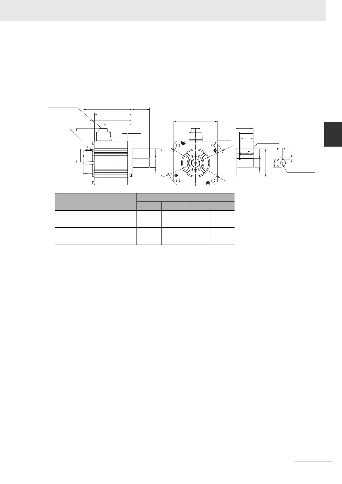
2-4-2 Servomotor Dimensions
4 kW/5 kW (without Brake)
R88M-KE4K020H (-S2)/-KE5K020H (-S2)
4 kW/5 kW (with Brake)
R88M-KE4K020H-B (S2)/-KE5K020H-B (S2)
Note The standard models have a straight shaft. Models with a key and tap are indicated with S2 at the end of the
model number.
Models with an oil seal are indicated with O at the end of the model number. The motor dimensions do not
change.
Model
Dimensions [mm]
LL LM KB1 KB2
R88M-KE4K020 178 133 96 158
R88M-KE5K020 197 152 115 177
R88M-KE4K020-B 207 162 96 187
R88M-KE5K020-B 226 181 115 206
Encoder
connector
Motor and brake
connector
LM
KB2
KB1
70LL
140
84
176
70
55
50
M3, through
(Shaft end specifications
with key and tap)
3.218
ø114.3h7
4-ø13.5
ø200
ø233
ø35h6
ø35h6
ø114.3h7
M12 depth 25
10h9
8
30
 Loading...


