2 - 39
2 Models and External Dimensions
OMNUC G5-series (Pulse-train Input Type) AC Servomotors and Servo Drives User’s Manual
2-4 External and Mounting Dimensions
2
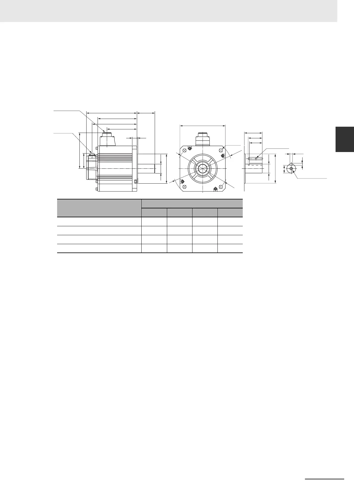
2-4-2 Servomotor Dimensions
2 kW/3 kW (without Brake)
R88M-KE2K010H (-S2)/-KE3K010H (-S2)
2 kW/3 kW (with Brake)
R88M-KE2K010H-B (S2)/-KE3K010H-B (S2)
Note The standard models have a straight shaft. Models with a key and tap are indicated with S2 at the end of the
model number.
Models with an oil seal are indicated with O at the end of the model number. The motor dimensions do not
change.
Model
Dimensions [mm]
LL LM KB1 KB2
R88M-KE2K010 164.5 119.5 82.5 144.5
R88M-KE3K010 210.5 165.5 128.5 190.5
R88M-KE2K010-B 193.5 148.5 82.5 173.5
R88M-KE3K010-B 239.5 194.5 128.5 219.5
Encoder
connector
Motor and brake
connector
LM
KB2
KB1
80
LL
140
84
176
80
55
50
M3, through
(Shaft end specifications
with key and tap)
3.218
ø35h6
ø35h6
ø114.3h7
4-ø13.5
ø200
ø233
ø114.3h7
M12 depth 25
10h9
8
30
 Loading...


