•
When using the external Regenerative Braking Unit, remove the built-in resistor. Using the
Regenerative Braking Unit with the built-in resistor connected may cause damage to the
built-in resistor.
•
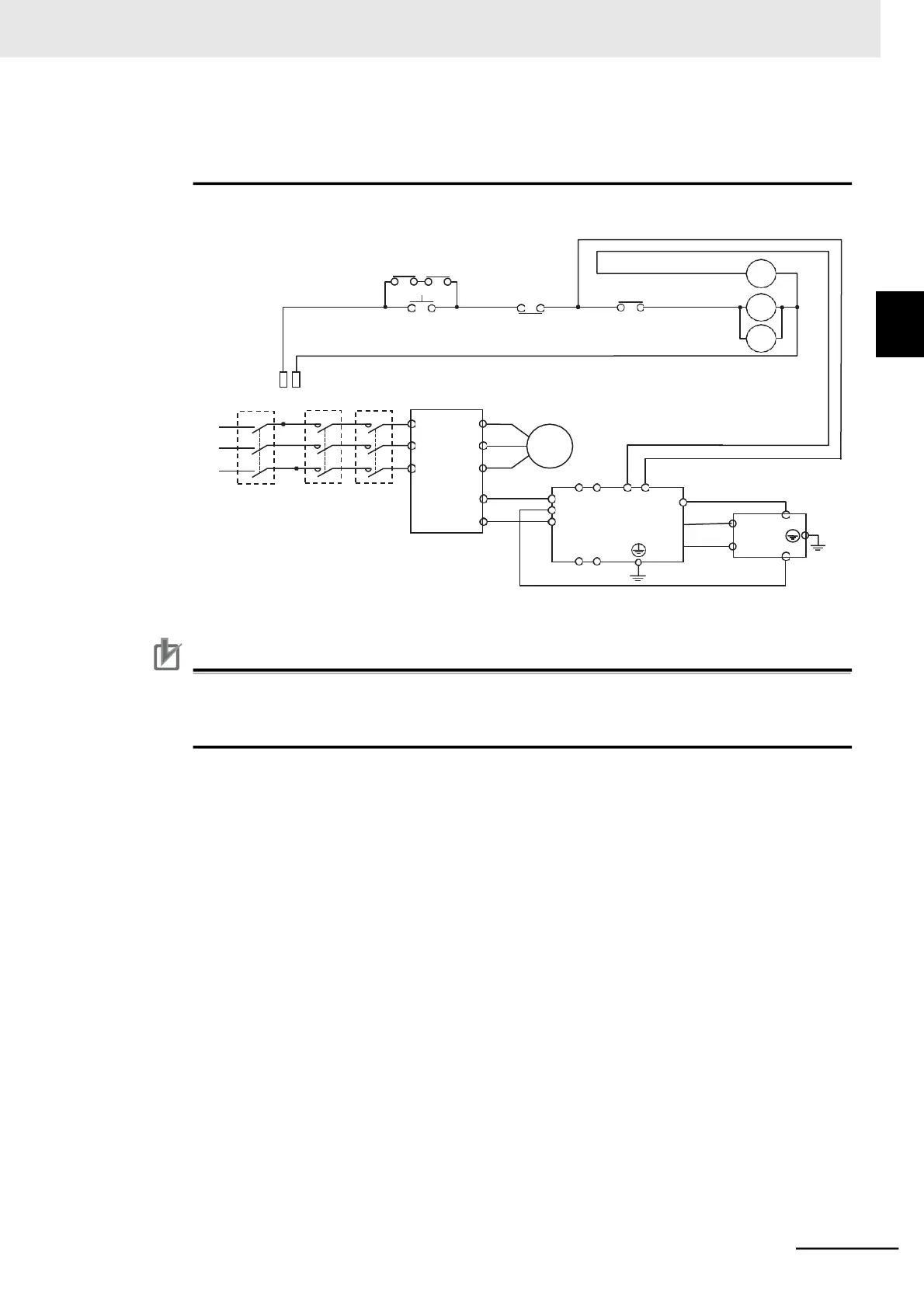
Wiring diagram for connecting one Braking Unit.
MC1 MC2
ON
OFF
RY
*1
RY
MC1
MC2
MCCB
R
S
T
Fuse
MC1
MC2
*2
Inverter
Motor
3-phase 200 V
Regenerative
br
*1. For RY, select the contact rating according to the ratings of the coils MC1 and MC2.
*2. MC1 and MC2 are used to provide redundancy.
Precautions for Correct Use
•
Each braking resistor has alarm contact (thermal relay output) terminals. Be sure to perform
wiring for these terminals so that alarm in the system is generated when overtemperature is
detected.