Multi-function Compact Inverter 3G3MX2-EV2 User’s Manual (I666-E1)
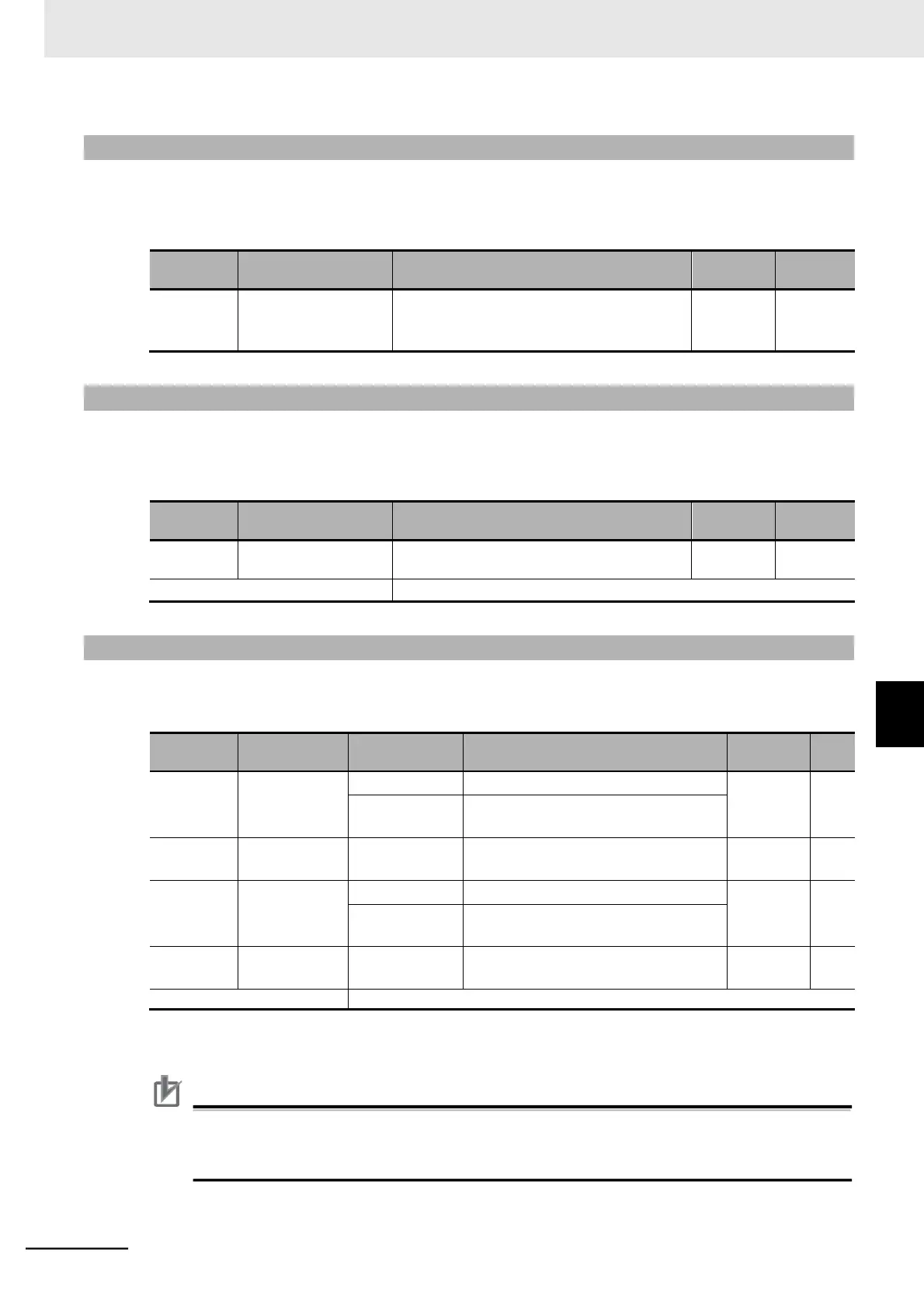
7-6-7 Inverter Display on Operator Connection
Once you connect the Inverter to the optional Digital Operator (Model: 3G3AX-OP01), the built-in Digi-
tal Operator keys will be disabled. Use this function to set the parameter to display on the built-in Digital
Operator at this time.
Inverter Display on
Operator Connection
001 to 060
Each data corresponds with the monitor mode
parameters d001 to d060.
7-6-8 Display Fixed (DISP)
Setting the Multi-function Input 1 to 7 Selection (C001 to C007) to 86 (DISP) and turning ON the cor-
responding terminal causes the Digital Operator to display only the content selected in the Initial Screen
Selection (b038), preventing it from displaying other parameters.
Multi-function Input 1
to 7 Selection
7-6-9 Password Function
Use the password function to set passwords for the Display Selection (b037) and Soft Lock Selection
(b031) functions to prevent display and change of the parameter settings.
Password function disabled.
*1
Set the password A for the Display
Selection (b037).
*2
Password A for
Authentication
Set the password A authentication
parameter.
*2
Password function disabled.
*1
Set the password B for the Soft Lock
Selection (b031).
*2
Password B for
Authentication
Set the password B authentication
parameter.
*2
*1. These passwords cannot be set to 0000.
*2. You can use any of the following 16 (hex) characters for parameter setting: 0 to 9, A, b, C, d, E, F.
Precautions for Correct Use
Be sure not to forget the set password. Note that there is no way to reset the password lock
once you forget the set password and even OMRON factories and service stations have no
means to check your password.
7-6 Digital Operator and Operation Functions
7-6-7 Inverter Display on Operator Connection