7-10-3 Wiring and Usage of the Safety Function
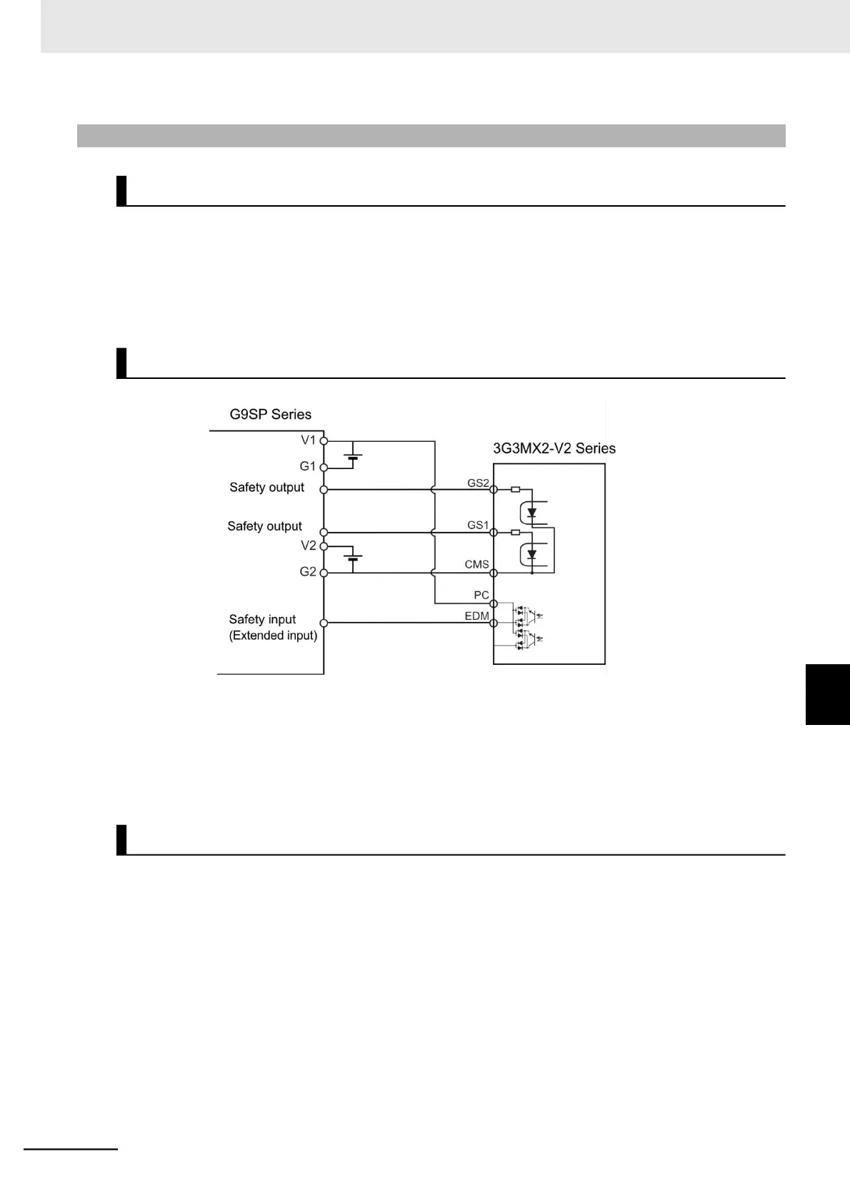
The Inverter has two inputs GS1 and GS2 for redundant input of the STO signals.
When power is applied to both input terminals and current flows, the safety paths permit the Inverter to
operate.
However, when voltage is not applied to at least one of the input terminals, the corresponding shutoff
path shuts off the Inverter output.
If you connect more than one G9SP-series safety controller or other safety devices, use them within the
guaranteed operation range of the devices used according to the above figure.
You cannot use the test pulses of the G9SP-series safety controllers for the GS1 and GS2 terminals. If
you do so, the compliance levels of entire system will be Cat 3/PLd and SIL 2.
The Inverter does not have a safety circuit with a function to hold the shutoff status of the internal safety
paths after STO input is reset.
Therefore, if the RUN command is input after STO input is reset, or if STO input is reset while it remains
ON, the Inverter starts output to the motor. Therefore, to comply with the emergency stop reset require-
ment of EN/IEC 60204-1, it is required that the system executes one of the following.
a.
Stops the RUN command to the Inverter when the STO is enabled, and gives the RUN command
when the system operator intentionally makes a request to restart the Inverter.
b.
Resets STO input when the system operator intentionally makes a request to restart the Inverter.