6 Vector Control and Applied Functions
Multi-function Compact Inverter 3G3MX2-EV2 User’s Manual (I666-E1)
6-1-4 Adjustments for Sensorless Vector Control
•
To use sensorless vector control method, perform offline auto-tuning.
If you cannot perform offline auto-tuning, set motor parameters appropriately according to 6-1-3
Motor Parameter Settings on page 6-9.
•
The inverter may not provide sufficient performance characteristics if your motor is two or more sizes
smaller than the maximum applicable motor capacity. This is because the inverter requires a current
accuracy of at least 50% of the rated current.
•
If the sensorless vector control method does not provide the intended performance characteristics,
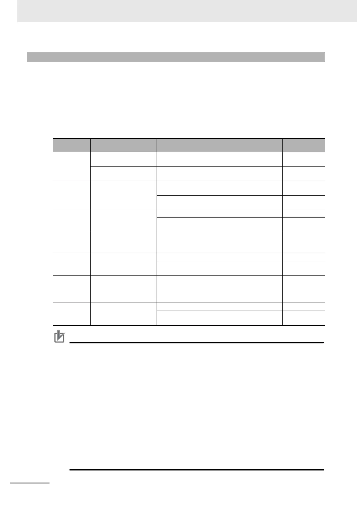
adjust the appropriate motor parameter depending on the phenomenon, as shown in the following table.
Actual motor speed is
lower than target speed.
Increase the Motor Parameter R2 value gradually,
up to 120% of the set value.
Actual motor speed is
higher than target speed.
Decrease the Motor Parameter R2 value gradually,
up to 80% of the set value.
Torque is insufficient at low
frequencies (a few Hz).
Increase the Motor Parameter R1 value gradually,
up to 120% of the set value.
Increase the Motor Parameter Io value gradually,
up to 120% of the set value.
Shock occurs during
startup.
Decrease the Speed Response value.
Decrease the Motor Parameter J value gradually,
relative to the set value.
Motor rotates momentarily
in opposite direction to
specified rotation direction.
Set the Reverse Rotation Prevention Selection
(b046) to 01 (Enabled).
Decrease the Speed Response value.
Decrease the Motor Parameter J value gradually,
relative to the set value.
Torque becomes insuffi-
cient at low frequencies
when torque limit is
enabled.
Decrease the torque limit.
Increase the Speed Response value.
Increase the Motor Parameter J value gradually,
relative to the set value.
Precautions for Correct Use
•
Before adjusting the 1st/2nd Speed Response (H005/H205), calculate the motor-shaft con-
version of the moment of load inertia, add the moment of inertia of the motor to it, and set the
sum in the 1st/2nd Motor Parameter J (H024/H224/H034/H234).
For 1st/2nd Speed Response (H005/H205), the larger the set value, the higher the response
speed, which results in a steep torque rise; the smaller the set value, the lower the response
speed, which results in gradual torque rise.
•
If you use a motor one size lower than the maximum applicable motor capacity for the
inverter, to prevent motor burnout, set the Torque Limit 1 to 4 (b041 to b044) to limit values
less than the value calculated from the following formula, then enable the torque limit func-
tion. For details on the torque limit function, refer to 6-2-1 Torque Limit Function Settings on
page 6-12.
Torque Limit set value (max.) = 200% [Rated motor current] / [Rated output current of inverter]
(Example) If the Inverter capacity and the motor capacity are 0.75 kW (rated output current =
5.0 A) and 0.4 kW (rated current = 2.3 A), respectively, set the torque limit values
below the following:
Torque Limit set value (max.) = 200% (2.3 A) / (5.0 A) = 92%