Multi-function Compact Inverter 3G3MX2-EV2 User’s Manual (I666-E1)
2-3-3 Arrangement and Function of Control Circuit Terminal Block
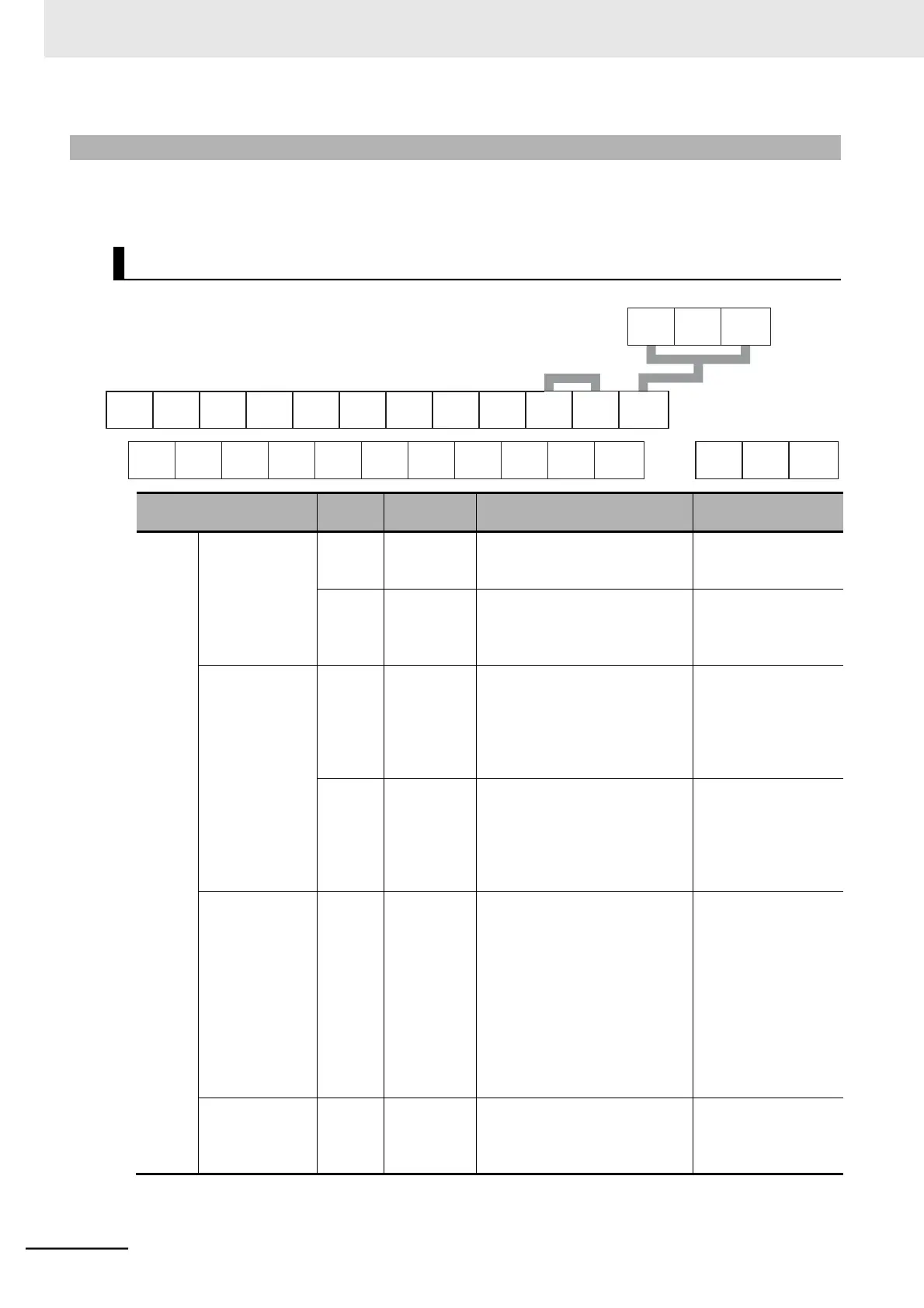
The table below shows the arrangement of the control circuit terminal block, and description and speci-
fications of each terminal.
Short-circuit bar
(for sink logic)
Short-circuit bar
(for disabling
STO function)
Common terminal for the internal
power supply, digital input, and
This is 10 VDC power supply for
Frequency set-
ting input
This is 0 to 10 VDC analog volt-
age input.
Input impedance:
Approx. 10 k
By default, this is adjusted so
that the frequency reaches the
maximum at 9.8 V. (Adjustable in
age range:
−0.3 to +12 VDC
This is 4 to 20 mA analog DC
input.
Input impedance:
Approx. 100
By default, this is adjusted so
that the frequency reaches the
maximum at 19.8 mA. (Adjust-
Set the Multi-function Input 5
Selection (C005) to 19 (TH: PTC
thermistor thermal protection) to
Connect an external thermistor
between this terminal and L,
and the inverter will trip if a tem-
perature error occurs. (The
inverter trips when the resistance
of the thermistor is approximately
3 k or higher.)
This terminal can output the
specified signal as a 0 to 10-VDC
Control Circuit Terminal Block